


Every crushing flowsheet is really an answer to one question: how do you get from a 400 mm shot rock to a 10 mm product? You cannot do it in one bite. Each machine has a limited reduction ratio, and stringing the right number of stages together — no more, no fewer — is what separates a plant that makes spec cheaply from one that chokes, wastes energy, or makes badly shaped stone.
This article makes that intuition quantitative. We define reduction ratio properly, show how stages multiply, and work two flowsheet examples — a generic three-stage plant and a real 0–20 mm quarry circuit — before listing the traps that catch operators who try to do too much with too few machines.
Defining reduction ratio
The size-reduction ratio compares feed and product on the same basis — the 80% passing sizes:

where  and
and  are the sieve sizes through which 80% of the feed and product pass. A second, machine-level limit is the limiting reduction ratio, roughly the gape divided by the closed-side setting (
 ) — you cannot ask a crusher for more than its geometry allows.
/ ignore the few stray oversize lumps that dominate a top-size figure, so the ratio reflects the bulk of the material the circuit actually processes.Stages multiply
Crushers in series multiply their ratios. For three stages,

so the number of stages needed for an overall ratio at an average per-stage ratio  is
is  . Each crusher type sits in a characteristic band:
| Crusher | Typical per-stage reduction | Role |
|---|---|---|
| Jaw / gyratory | 4 : 1 to 7 : 1 | Primary |
| Standard cone | 3 : 1 to 5 : 1 | Secondary |
| Short-head cone / VSI | 2 : 1 to 4 : 1 | Tertiary / shaping |
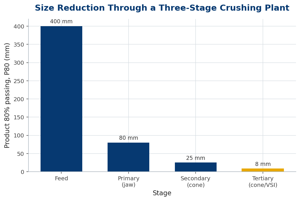
Worked example 1 — how many stages?
Feed  , target
  :
:

At a conservative average  ,
,  — round up to three stages. A jaw (
 ) then two cones (
 and
and  ) gives
  , comfortably above 40 with margin for the closed-circuit tertiary.
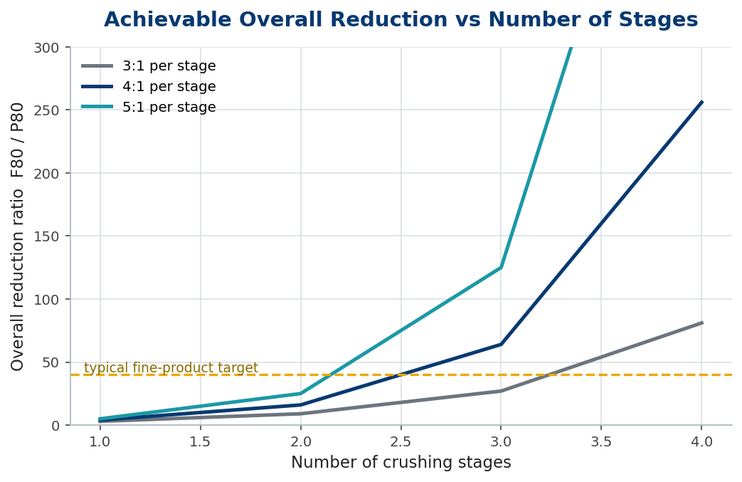
Why not fewer, bigger bites?
Push a single crusher past its reduction band and three things go wrong: the chamber packs (capacity falls and power spikes), product shape worsens (more flaky particles), and liner wear climbs. Figure 2 shows why fine products essentially demand three stages — the achievable overall ratio only clears a typical 40:1 target once you reach three stages, even at an optimistic 4–5:1 per stage.
Worked example 2 — a 0–20 mm quarry circuit
Blasted rock at  into a 0–20 mm product (
 ) needs
  . A jaw at drops to ~90 mm; a secondary cone at to ~22 mm; a closed-circuit tertiary at finishes the job and recirculates oversize. The closed tertiary is also where you control top size precisely — see the companion article on circulating load.
Splitting the ratio between stages
An overall ratio of 40 can be reached many ways —  ,
,  , or
, or  . The split matters. Equalising the per-stage ratio (the geometric-mean choice,
  ) spreads energy and wear evenly and usually gives the best overall product shape. Front-loading the primary squeezes more from the cheapest machine but risks packing; back-loading leans on the tertiary, raising its circulating load and liner cost.
| Strategy | Stage ratios (R<sub>total</sub> = 40) | Trade-off |
|---|---|---|
| Equalised | 3.4 : 3.4 : 3.4 | even wear & energy, best shape |
| Front-loaded | 6 : 3.3 : 2 | fewer tertiary fines, but primary packs |
| Back-loaded | 3 : 3 : 4.4 | gentle primary, high tertiary load |
For  over
over  stages the equalised ratio is
  per stage — a sensible default to perturb from once you know which machine is your real bottleneck.
In practice
On a real flowsheet the stage ratios are rarely shared evenly. The primary is usually run conservatively (4–5:1) to protect product shape and the toggle, while the tertiary — in closed circuit — carries the variable duty that trims top size to spec. Three habits keep a staged plant honest:
- Balance the stages to wear, not just size. A primary set too tight to save a whole stage wears jaws fast and starves the secondary of well-graded feed.
- Let the last stage shape. Tertiary cones and VSIs earn their place on cubicity; judge them on flakiness index, not only on reduction.
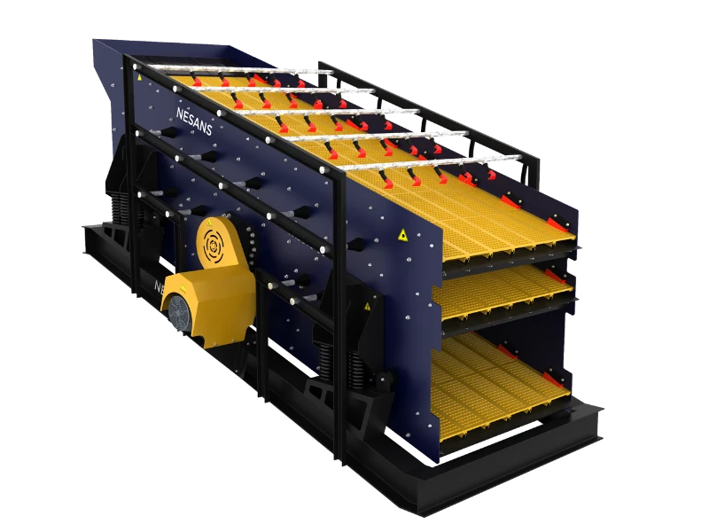
- Design the closed circuit for the recycle. The tertiary and its screen see fresh feed plus circulating load, so size them to the combined stream, never the fresh feed alone.
Common mistakes
- Over-reducing in the primary. A jaw asked for 9:1 packs and makes slabby stone; keep it inside 6–7:1.
- Forgetting the gape/CSS limit. The reduction you want must also be one the geometry allows.
- Skipping the shaping stage. The last stage often exists for cubicity, not size — drop it and flakiness suffers.
Frequently asked questions
What is the maximum reduction ratio of a jaw crusher?
Around 6:1 in routine operation. Higher ratios are possible momentarily but pack the chamber and degrade shape and capacity.
Why use F80 and P80 rather than top size?
The 80%-passing sizes describe the bulk of the stream and are insensitive to a handful of oversize lumps, so the ratio is repeatable.
Can I replace three crushers with one high-reduction machine?
Rarely well. Single-stage high reduction costs energy, shape and liner life; staged crushing is almost always cheaper per tonne to spec.
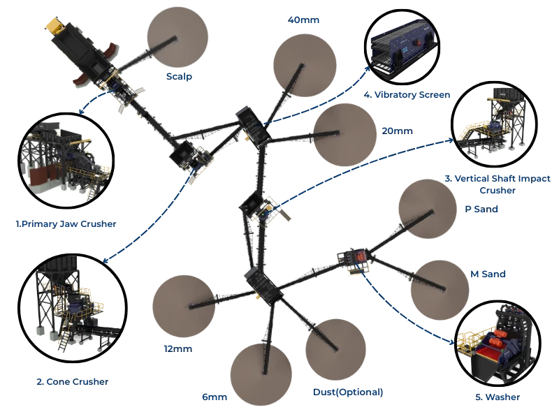
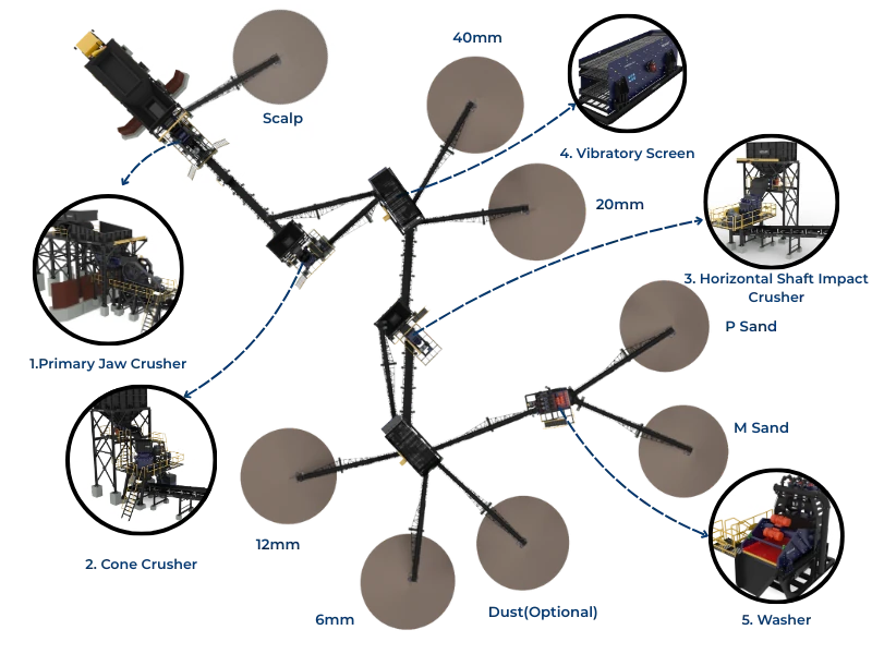
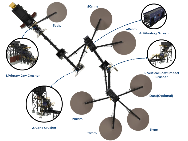
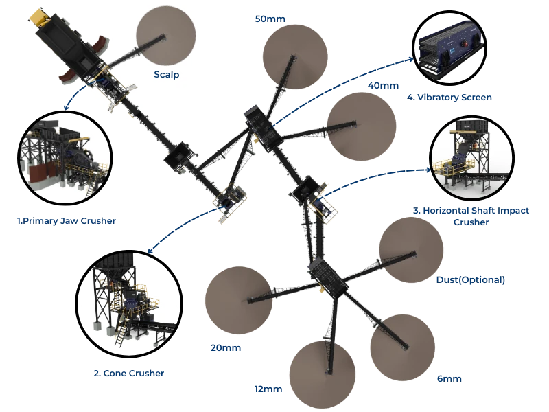
Matching a crusher type to each stage
Splitting the reduction between stages only works if each stage uses a crusher suited to its bite. Reduction ratio is not a free choice — each crusher family has a comfortable range, and pushing it past that range wears parts fast and makes poor product. So the flowsheet is really a sequence of machine choices, each matched to the ratio its stage must deliver.
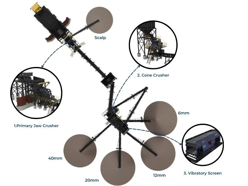
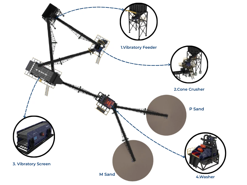
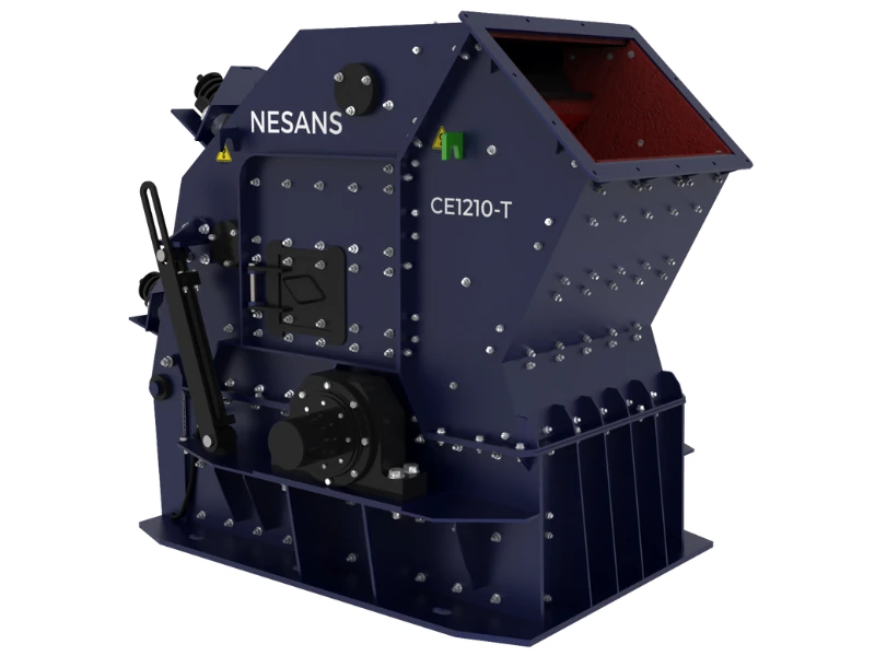
The primary takes the run-of-quarry feed and makes the first, coarse reduction, typically around 4:1 to 6:1. A jaw crusher suits most quarries here for its simplicity and tolerance of large, blocky, slabby feed; a gyratory earns its higher cost only at very high tonnages where its continuous action pays. The secondary and tertiary stages then refine the product, and the cone crusher owns this ground — good reduction (3:1 to 5:1 per stage), good capacity and a controllable product.
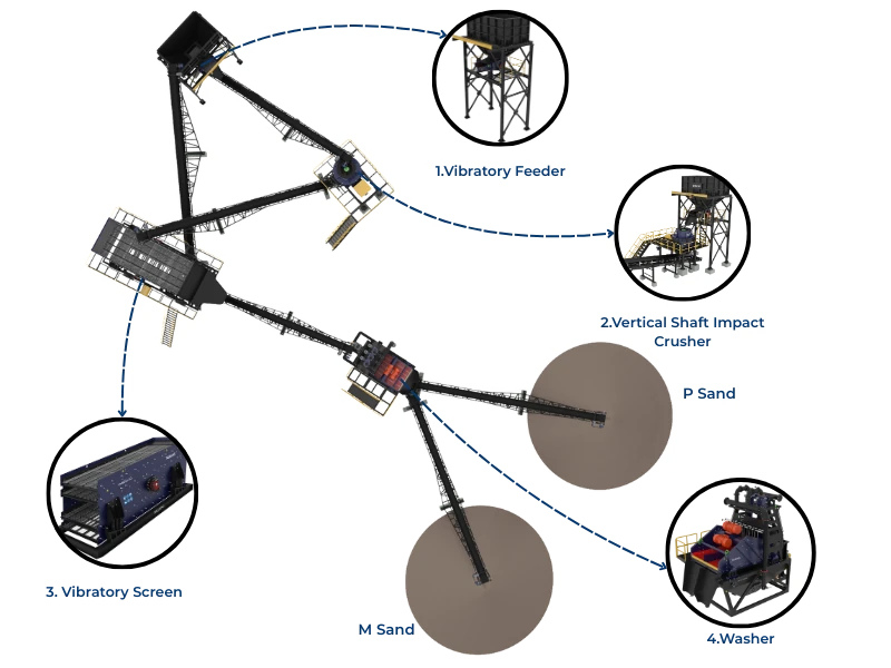
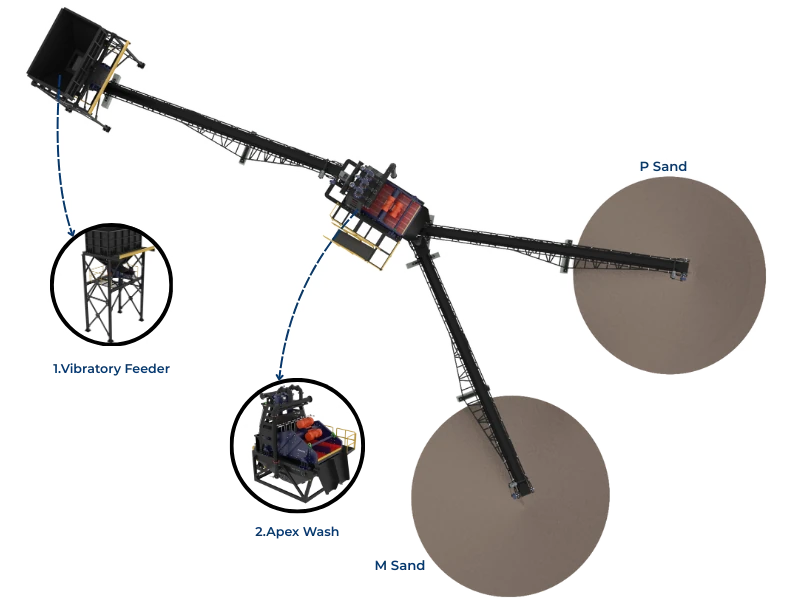
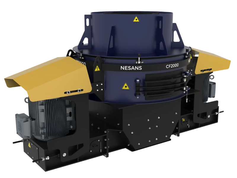
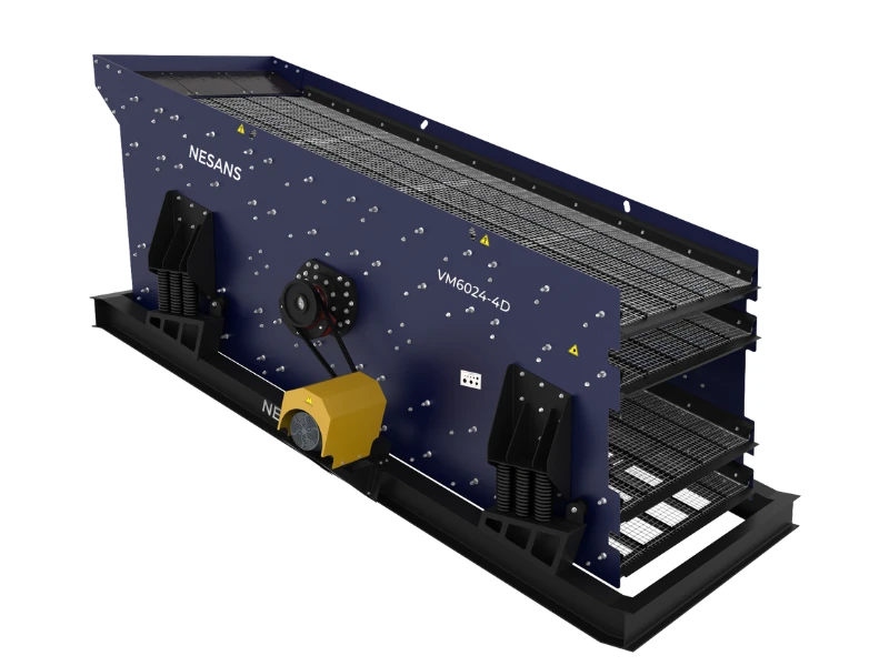
Where product shape matters — manufactured sand, premium aggregate — a vertical-shaft impactor takes the final stage, trading reduction for cubicity. And ahead of it all, a scalping grizzly removes the feed that is already fine enough, so the primary’s reduction is spent only on rock that needs it. Each machine is chosen for the bite its stage demands, not dropped in interchangeably.
This is why two plants with the same overall reduction can look completely different: one jaw-cone-cone for bulk aggregate, another jaw-cone-VSI for shaped sand. The stage count sets how many bites; the machine choice at each stage sets how that bite is taken — and getting both right is what keeps every crusher inside its comfortable ratio, where wear is low and product is good.
The bottom line
Reduction ratio is the arithmetic behind every flowsheet decision. Fix the overall ratio from feed and product, divide it sensibly across stages within each machine’s limits, and you arrive at a plant that makes spec at the lowest energy and wear. Try to shortcut it — one big crusher, a primary run too tight, a missing shaping stage — and the cost reappears as packing, flaky stone or short liner life.
Treat the closed tertiary as the precision stage, and size it together with its screen for the recirculated stream rather than the fresh feed. Do that and the circuit holds top size cleanly across the inevitable swings in feed.
Key takeaways
- Reduction ratio
 ; stages multiply,
  .
. - Per-stage ratios are bounded (~4–7:1 jaw, 3–5:1 cone, 2–4:1 VSI) by geometry and shape.
- Fine products generally need three stages; pushing fewer, bigger bites packs chambers and ruins shape.
- Always check the wanted ratio against the gape/CSS limit before committing a flowsheet.