


Your mobile crushing equipment arrives at the quarry site—₹3-5 crore worth of machinery ready for deployment. But within the first week, you're facing constant track sinking in soft ground, equipment spacing that causes material spillage, power generators overloading, and dust complaints from the village 500 meters away. The crushing performance you expected—150-200 TPH of quality aggregate—drops to 80 TPH with frequent stoppages. The problem isn't the equipment; it's the setup. Proper mobile crushing plant setup, from site selection to commissioning, determines whether your investment delivers projected returns or becomes a costly lesson in planning failures.
Mobile crushing plants offer significant advantages over stationary installations: rapid deployment, flexibility to follow material sources, lower initial infrastructure costs, and the ability to relocate when quarry faces change or contracts end. However, these advantages only materialize when site selection, layout planning, and setup procedures follow systematic engineering approaches rather than improvised decisions made under time pressure.
This comprehensive guide covers every aspect of mobile crushing plant setup, from initial site evaluation through first production. We provide specific technical parameters, layout dimensions, infrastructure requirements, and commissioning procedures based on hundreds of successful installations across India. Whether deploying a single mobile jaw crusher or a complete multi-stage mobile plant, this guide ensures your setup maximizes equipment performance while minimizing operational problems.
Chapter 1: Site Selection Fundamentals
1.1 Ground Conditions and Load-Bearing Requirements
Mobile crushing equipment exerts substantial ground pressure that many unprepared sites cannot sustain. Understanding load-bearing requirements prevents track sinking, equipment tilting, and structural damage that can sideline operations for weeks.
Equipment Weight and Ground Pressure Data:
| Equipment Type | Operating Weight (tons) | Track Length (m) | Track Width (m) | Ground Pressure (kg/cm²) |
|---|---|---|---|---|
| Mobile Jaw Crusher (40x24) | 45-55 | 4.2 | 0.6 | 0.55-0.65 |
| Mobile Jaw Crusher (48x36) | 65-80 | 4.8 | 0.7 | 0.60-0.70 |
| Mobile Cone Crusher (300) | 55-70 | 4.5 | 0.6 | 0.58-0.68 |
| Mobile Cone Crusher (400) | 75-95 | 5.2 | 0.7 | 0.62-0.72 |
| Mobile VSI Crusher | 50-65 | 4.3 | 0.6 | 0.55-0.65 |
| Mobile Screen (6x20 3-deck) | 40-50 | 4.0 | 0.6 | 0.50-0.60 |
| Wheel-Mounted Jaw | 35-45 | N/A | N/A | Point loads at outriggers |
Soil Bearing Capacity Requirements:
| Soil Type | Typical Bearing Capacity (kg/cm²) | Suitability | Ground Preparation Required |
|---|---|---|---|
| Hard rock surface | 10-25+ | Excellent | Level only, no preparation needed |
| Compacted gravel/crushed stone | 2.5-4.0 | Excellent | Ensure 300mm minimum depth |
| Dense sand/gravel mix | 1.5-2.5 | Good | Compact to 95% Modified Proctor |
| Stiff clay | 1.0-2.0 | Acceptable | Add 200mm crushed stone layer |
| Firm clay | 0.5-1.0 | Marginal | Requires 400mm aggregate base |
| Soft clay | 0.25-0.5 | Poor | Geotextile + 500mm aggregate |
| Loose sand | 0.5-1.0 | Poor | Compact + 300mm aggregate cap |
| Organic soil/fill | <0.5 | Unsuitable | Excavate and replace completely |
Ground Investigation Procedure:
- Visual Assessment: Look for standing water, soft spots, previous excavations, vegetation indicating high water table
- Hand Auger Test: Bore to 1.5m depth at equipment locations to check soil consistency and water table
- Plate Load Test: For critical installations, conduct plate bearing test per IS 1888 to verify bearing capacity
- Dynamic Cone Penetrometer: Quick field test correlating to CBR value and bearing capacity
- Seasonal Consideration: Assess conditions during monsoon if operations will continue year-round
Ground Preparation Specifications:
For sites requiring ground improvement before mobile crusher deployment:
| Existing Condition | Preparation Method | Material Specification | Compaction Requirement | Estimated Cost (₹/m²) |
|---|---|---|---|---|
| Soft clay (CBR <3) | Geotextile + aggregate | 40mm crushed aggregate, 500mm depth | 95% Modified Proctor | 800-1,200 |
| Firm clay (CBR 3-7) | Aggregate pad | 40mm aggregate, 300mm depth | 95% Modified Proctor | 500-700 |
| Loose sand | Compact + cap | Vibratory compaction + 200mm aggregate | 98% relative density | 350-500 |
| Mixed fill | Proof roll + repair | Identify soft spots, replace with aggregate | No deflection under loaded truck | 200-400 |
⚠️ Critical Warning: Never position mobile crushing equipment on unprepared soft ground "temporarily" with plans to improve later. Track systems can sink 300-500mm overnight under static weight alone, requiring heavy recovery equipment and causing track mechanism damage costing ₹5-15 lakhs to repair.
1.2 Access Road Requirements
Mobile crushing equipment transport requires careful route planning. Low-bed trailers carrying tracked crushers create exceptional loads that many rural roads cannot support.
Transport Vehicle Specifications:
| Equipment | Transport Configuration | Gross Vehicle Weight (tons) | Overall Length (m) | Overall Width (m) | Height (m) |
|---|---|---|---|---|---|
| Mobile Jaw Crusher | 14-axle hydraulic trailer | 80-110 | 22-28 | 3.5-4.0 | 4.2-4.5 |
| Mobile Cone Crusher | 14-axle hydraulic trailer | 90-120 | 24-30 | 3.5-4.0 | 4.0-4.5 |
| Mobile Screen | 10-axle low-bed | 60-80 | 20-24 | 3.2-3.5 | 4.0-4.2 |
| Wheel-Mounted Unit | Self-propelled or 6-axle | 45-60 | 16-20 | 3.0-3.2 | 4.0-4.2 |
Road and Bridge Requirements:
- Road Width: Minimum 6m for straight sections, 8m for curves
- Curve Radius: Minimum 25m for 14-axle trailers, 15m for smaller units
- Gradient: Maximum 8% for loaded climb, 10% for descent with braking
- Bridge Capacity: Verify IRC Class AA or 70R rating for heavy equipment
- Overhead Clearance: Minimum 5m for standard equipment, check actual heights
- Culvert Capacity: Most rural culverts rated for 20-ton axle loads—hydraulic trailers exceed this
Route Survey Checklist:
- Drive entire route in daylight, noting potential obstacles
- Measure overhead restrictions (power lines, bridges, tree canopy)
- Identify narrow sections requiring traffic control or widening
- Check bridge and culvert capacities with local PWD records
- Note soft shoulders that prevent passing oncoming traffic
- Identify turnaround points if route becomes impassable
- Confirm night transport permissions if required for traffic management
- Coordinate with electricity board for power line lifting if needed
1.3 Environmental and Regulatory Considerations
Distance Requirements from Sensitive Receptors:
| Receptor Type | Minimum Distance (m) | Regulatory Basis | Mitigation if Closer |
|---|---|---|---|
| Residential area (>25 houses) | 500 | TNPCB/KSPCB guidelines | Enhanced dust control, barriers |
| Individual houses | 200 | State PCB norms | Dust screens, limited hours |
| Schools, hospitals | 500 | Environmental clearance | Not typically permitted closer |
| Water bodies (rivers, tanks) | 100 | CRZ/water body protection | Sediment control, no washing |
| Reserved forest | Site-specific | Forest clearance | As per FC conditions |
| National highways | 75 | NHAI building line | Setback compliance |
| State highways | 30-50 | State PWD norms | As per state rules |
| Agricultural land boundary | 50 | Good practice | Dust barriers, drainage control |
Permits and Clearances Required:
| Permit/Clearance | Issuing Authority | Typical Timeline | Validity |
|---|---|---|---|
| Mining lease/quarry permit | Dept. of Mines & Geology | 6-18 months | 5-20 years |
| Environmental clearance | SEIAA or MoEF&CC | 3-12 months | Project life (typically 30 years) |
| Consent to Establish | State PCB (TNPCB/KSPCB) | 1-3 months | Until commissioning |
| Consent to Operate | State PCB | 1-2 months | 1-5 years renewable |
| Factory license | Dept. of Factories | 1-2 months | Annual renewal |
| Explosive license (if blasting) | PESO (Dept. of Explosives) | 2-4 months | 1-3 years |
| Water extraction permission | CGWB/State GW Authority | 1-3 months | 1-5 years |
| Transport permit (over-dimension) | RTO | 1-2 weeks per trip | Single journey |
⚠️ Important: Mobile crushing plants operating on mining leases typically fall under the existing environmental clearance of the quarry/mine. However, standalone mobile operations (contract crushing, C&D waste recycling) may require separate environmental clearance depending on capacity and location. Verify requirements with State PCB before equipment mobilization.
1.4 Raw Material Access and Quality
Site selection must ensure consistent raw material supply meeting crusher feed requirements.
Feed Material Accessibility Factors:
- Haul Distance: Optimal <500m from face to crusher; up to 1,500m acceptable with adequate loader fleet
- Vertical Lift: Minimize elevation difference; each 10m lift adds 15-20% to haul cycle time
- Face Accessibility: Ensure excavator/loader can work safely at quarry face
- Bench Height: Match to excavator capability—typically 6-10m benches
- Multiple Feed Points: For large operations, position crusher to receive from multiple faces
Material Quality Considerations:
| Material Property | Acceptable Range | Impact if Outside Range | Testing Method |
|---|---|---|---|
| Abrasion Index (Ai) | 0.1-0.5 | High wear costs if >0.5 | ASTM C535 |
| Crushing Work Index (CWi) | 8-15 kWh/ton | Capacity reduction if >15 | Bond Crushing Work Index |
| Moisture Content | <5% | Handling problems, screen blinding if >8% | IS 2386 Part 3 |
| Clay Content | <3% | Product contamination, screen blinding | Sand equivalent test |
| Maximum Feed Size | 80% of crusher opening | Bridging, reduced capacity | Visual assessment |
| Compressive Strength | 50-250 MPa | Equipment selection varies | IS 9143 |
Chapter 2: Equipment Selection for Mobile Plants
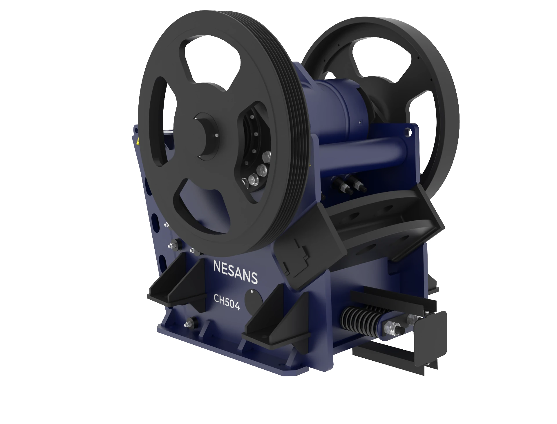
2.1 Primary Mobile Jaw Crushers
The mobile jaw crusher forms the foundation of most mobile crushing operations, handling run-of-mine material and producing feed for secondary stages.
Mobile Jaw Crusher Selection Guide:
| Parameter | NMJ-4024 Series | NMJ-4836 Series | Application |
|---|---|---|---|
| Feed Opening | 1000 x 600mm | 1200 x 900mm | Larger opening for poorly fragmented rock |
| Maximum Feed Size | 800mm | 1000mm | Match to blasting fragmentation |
| Capacity Range | 100-180 TPH | 180-350 TPH | Match to target production |
| CSS Range | 75-200mm | 100-250mm | Smaller CSS = finer product, lower capacity |
| Engine Power | 250-300 HP | 400-500 HP | Higher power for harder rock |
| Operating Weight | 45-55 tons | 65-80 tons | Affects transport and ground requirements |
| Transport Width | 2.9-3.2m | 3.2-3.5m | Route accessibility considerations |
| Fuel Consumption | 25-35 L/hr | 40-55 L/hr | Operating cost factor |
Key Selection Factors:
- Required Capacity: Select jaw crusher delivering 20-30% above target capacity to accommodate feed variations
- Feed Size Distribution: Match feed opening to expected maximum boulder size with 80% passing 80% of opening
- Product Requirements: Determine if jaw crusher product is final or feeds secondary—affects CSS setting
- Material Hardness: Harder rock (>200 MPa) requires heavier-duty frames and higher power
- Site Constraints: Transport route limitations may dictate maximum equipment size
Integrated Feeder Systems:
Mobile jaw crushers incorporate feeder systems that significantly affect performance:
- Vibrating Grizzly Feeder: Standard on most mobile jaws; grizzly bars scalp undersize (typically -40mm) to bypass crusher, increasing effective capacity 20-40%
- Grizzly Bar Spacing: Adjustable 40-100mm; set to bypass material smaller than CSS
- Feeder Width: Must exceed excavator bucket width for efficient loading
- Hopper Capacity: 6-12 m³ provides buffer for excavator cycling; larger hoppers for loader feeding
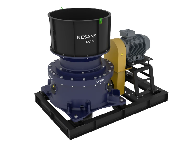
2.2 Secondary Mobile Crushers
Secondary crushing—whether cone, impact, or VSI—determines final product quality and gradation.
Mobile Cone Crusher Specifications:
| Parameter | NMC-300 Series | NMC-400 Series | Selection Criteria |
|---|---|---|---|
| Head Diameter | 900mm | 1200mm | Larger head = higher capacity |
| Feed Opening | 180mm | 220mm | Determines maximum feed from primary |
| Capacity (CSS 20mm) | 100-180 TPH | 180-300 TPH | Match to primary output |
| CSS Range | 10-40mm | 13-50mm | Finer CSS for smaller products |
| Power Requirement | 200-250 kW | 300-400 kW | Affects fuel consumption |
| Crushing Force | 150-200 tons | 250-350 tons | Higher force for harder rock |
| Operating Weight | 55-70 tons | 75-95 tons | Transport considerations |
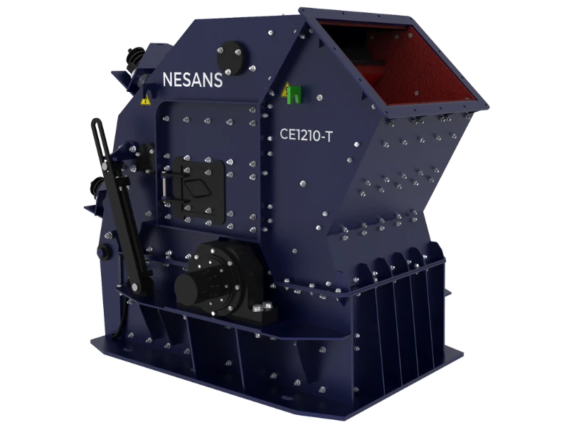
Mobile Impact Crusher Specifications:
| Parameter | NMI-1210 Series | NMI-1315 Series | Selection Criteria |
|---|---|---|---|
| Rotor Diameter | 1000mm | 1300mm | Larger rotor = higher capacity |
| Rotor Width | 1000mm | 1500mm | Wider rotor = better distribution |
| Feed Opening | 1000 x 800mm | 1300 x 1000mm | Can accept larger feed than cone |
| Capacity | 150-250 TPH | 250-400 TPH | Higher than equivalent cone |
| Power Requirement | 200-300 kW | 350-500 kW | Higher power consumption than cone |
| Blow Bar Weight | 80-120 kg each | 150-220 kg each | Wear cost consideration |
| Operating Weight | 50-65 tons | 70-90 tons | Generally lighter than equivalent cone |
Cone vs Impact Crusher Selection:
| Factor | Cone Crusher Preferred | Impact Crusher Preferred |
|---|---|---|
| Material Abrasiveness | High abrasion (Ai >0.3) | Low-medium abrasion (Ai <0.3) |
| Product Shape | Good cubical shape | Excellent cubical shape |
| Wear Cost | Lower per ton for abrasive rock | Higher for abrasive materials |
| Reduction Ratio | 4:1 to 6:1 typical | 10:1 to 15:1 possible |
| Fines Generation | Less fines (-4mm) | More fines generation |
| Capital Cost | Higher initial cost | Lower initial cost |
| Maintenance Complexity | More complex (hydraulics, liners) | Simpler (blow bar changes) |
| Ideal Application | Hard granite, basalt aggregates | Limestone, recycled concrete |
2.3 Mobile Screening Plants
Mobile Screen Selection by Application:
| Application | Screen Size | Deck Configuration | Capacity (TPH) | Cut Sizes |
|---|---|---|---|---|
| Primary scalping | 5' x 16' | Single or double deck grizzly | 300-500 | 75-150mm |
| Secondary classification | 6' x 20' | 2-3 inclined decks | 200-400 | 20, 10, 5mm |
| Final product screening | 6' x 20' | 3-4 horizontal decks | 150-300 | 20, 10, 6, 3mm |
| Sand washing/dewatering | 6' x 16' | Single deck high-frequency | 100-200 | Dewatering only |
| Recycling | 5' x 14' | Double deck with fingers | 150-250 | 75, 38mm |
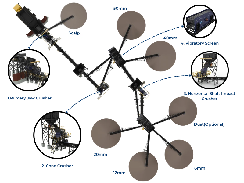
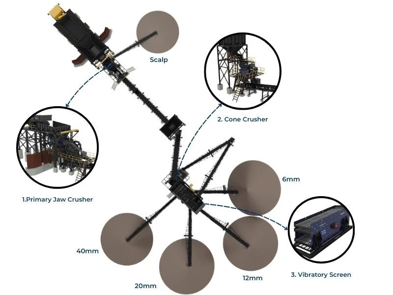
Screen Deck Configuration for IS 383:2016 Aggregates:
For producing graded aggregates meeting IS 383:2016 specifications:
| Deck Position | Screen Aperture | Product Generated | IS 383 Nominal Size |
|---|---|---|---|
| Top deck | 40mm | Oversize to recirculation or reject | Above graded limits |
| Second deck | 20mm | 20-40mm coarse aggregate | 40mm nominal |
| Third deck | 10mm | 10-20mm medium aggregate | 20mm nominal |
| Bottom deck | 4.75mm | 4.75-10mm fine aggregate | 10mm nominal |
| Underflow | N/A | 0-4.75mm crusher dust/sand | Fine aggregate |
2.4 Capacity Matching Principles
Proper capacity matching between crushing stages prevents bottlenecks and maximizes system efficiency.
Capacity Matching Rules:
| Stage Relationship | Capacity Ratio | Reasoning |
|---|---|---|
| Primary to Secondary | Primary 1.2-1.5x Secondary | Primary produces surge; secondary must keep up at peak |
| Secondary to Screen | Screen 1.3-1.5x Secondary | Screen handles return plus fresh feed |
| Screen to Tertiary | Tertiary sized for screen oversize | Typically 30-50% of screen feed |
| Feeding to Primary | Excavator 1.5-2.0x Primary | Excavator availability <100%; need overcapacity |
Example 200 TPH Aggregate Plant Sizing:
| Equipment | Sized Capacity | Expected Operating Rate | Utilization |
|---|---|---|---|
| Excavator (20T) | 350-400 TPH | 250-300 TPH | 60-75% |
| Mobile Jaw Crusher | 250-300 TPH | 200-220 TPH | 70-85% |
| Mobile Cone Crusher | 180-220 TPH | 150-180 TPH | 75-85% |
| Mobile Screen (3-deck) | 300-350 TPH | 220-280 TPH | 65-80% |
| Return Conveyor | 80-100 TPH | 40-60 TPH | 50-60% |
Chapter 3: Layout Planning and Optimization
3.1 Material Flow Principles
Optimal layout minimizes double-handling, reduces conveyor lengths, and provides safe access for operations and maintenance.
Layout Planning Priorities:
- Gravity Flow: Wherever possible, use gravity to move material—reduces power consumption and equipment
- Linear Progression: Arrange equipment in logical sequence following material transformation
- Minimize Transfers: Each transfer point adds cost, causes degradation, and creates dust
- Access Requirements: Ensure maintenance access to all equipment without moving other units
- Stockpile Space: Adequate room for product stockpiles without interfering with traffic
Minimum Spacing Requirements:
| Between Equipment | Minimum Distance (m) | Recommended Distance (m) | Purpose |
|---|---|---|---|
| Jaw crusher to cone crusher | 8 | 12-15 | Surge pile buffer, access |
| Crusher to screen | 6 | 8-12 | Conveyor angle, access |
| Screen to stockpiles | 10 | 15-20 | Radial stacker swing |
| Equipment to haul road | 6 | 10-15 | Safety, dust control |
| Between parallel equipment | 5 | 8-10 | Maintenance access |
| Equipment to site boundary | 15 | 25-30 | Buffer, future expansion |
Typical Mobile Plant Layout Options:
Option 1: Linear Layout
- Equipment arranged in straight line
- Simplest conveyor arrangement
- Best for narrow sites
- Requires approximately 80-100m length for 3-stage plant
- Feed from one end, stockpiles at other
Option 2: L-Layout
- Primary stage on one axis, secondary/tertiary on perpendicular axis
- Reduces overall site length to 50-60m
- Better suited for square/rectangular sites
- Allows feed from multiple directions
Option 3: Stacked/Compact Layout
- Equipment positioned close together with elevated discharge
- Minimizes footprint (40x40m possible for 2-stage)
- Higher conveyor lifts required
- More challenging maintenance access
3.2 Conveyor Arrangements
Conveyor Design Parameters:
| Parameter | Primary Discharge | Secondary Feed | Product Stackout |
|---|---|---|---|
| Belt Width | 800-1000mm | 650-800mm | 500-650mm |
| Belt Speed | 1.5-2.0 m/s | 1.5-2.0 m/s | 2.0-2.5 m/s |
| Maximum Incline | 18° | 18° | 20° (radial stacker) |
| Typical Length | 10-15m | 8-15m | 15-25m |
| Drive Power | 15-30 kW | 11-22 kW | 7.5-15 kW |
| Trough Angle | 35° | 35° | 35° |
Transfer Point Design:
Transfer points between conveyors are critical for minimizing spillage, dust, and material degradation:
- Drop Height: Minimize free-fall to <1.5m where possible; use rock boxes for higher drops
- Chute Angle: Minimum 60° from horizontal for reliable flow
- Impact Zone: Install impact idlers and wear liners in loading zones
- Dust Enclosure: Full enclosure at transfers with dust extraction or suppression
- Belt Cleaners: Primary and secondary cleaners at all head pulleys
- Skirt Boards: Extended skirting (3-4m) at loading points to contain splash
3.3 Traffic Management
Site Traffic Layout Requirements:
| Traffic Type | Road Width | Gradient | Surface |
|---|---|---|---|
| Dump truck haul road | 10-12m (two-way) | <10% | Compacted aggregate |
| Loader operating area | 20-25m turning radius | <5% | Compacted aggregate |
| Light vehicle access | 4-5m | <15% | Gravel or aggregate |
| Emergency access | 4m minimum | <12% | All-weather surface |
| Stockpile loading | 15m loader operating | <5% | Heavy-duty surface |
Traffic Flow Principles:
- One-Way Circuits: Where possible, create one-way loops to minimize reversing
- Separation: Keep dump trucks and light vehicles on separate routes
- Visibility: Clear sightlines at intersections; remove stockpile or equipment obstructions
- Speed Control: Limit haul truck speeds to 20 km/hr; light vehicles to 15 km/hr
- Pedestrian Exclusion: Define no-walk zones around operating equipment
Chapter 4: Infrastructure Requirements
4.1 Power Supply Options
Mobile crushing plants typically operate on diesel power, but understanding all options enables optimal selection.
Power Source Comparison:
| Power Source | Typical Capacity | Cost per Unit | Advantages | Disadvantages |
|---|---|---|---|---|
| On-board diesel engines | 250-500 HP per unit | ₹18-22/kWh | Self-contained, mobile | High fuel cost, emissions |
| Diesel generator sets | 250-1000 kVA | ₹14-18/kWh | Centralized power, electric drives | Requires cables, less mobile |
| Grid connection (HT) | 500 kVA+ | ₹6-8/kWh | Lowest running cost | Infrastructure cost, not mobile |
| Hybrid (diesel + solar) | Site-specific | ₹10-14/kWh | Reduced fuel consumption | Higher capital, space needed |
Power Requirement Estimation:
| Equipment | Connected Load (kW) | Typical Demand (kW) | Power Factor |
|---|---|---|---|
| Mobile Jaw Crusher | 160-220 | 120-180 | 0.85 |
| Mobile Cone Crusher | 220-350 | 180-280 | 0.85 |
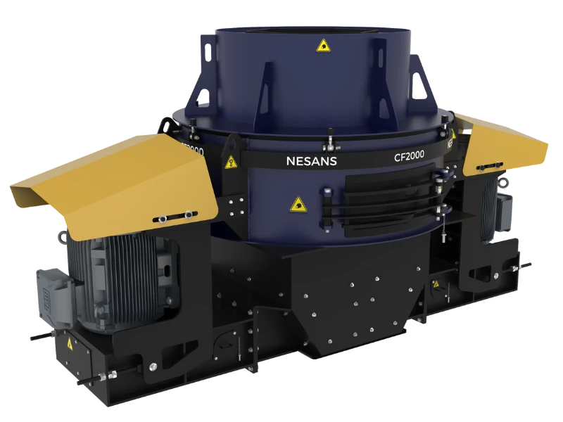
| Mobile VSI Crusher | 180-280 | 140-220 | 0.85 |
| Mobile Screen (3-deck) | 30-45 | 22-35 | 0.80 |
| Conveyors (each) | 11-30 | 8-22 | 0.80 |
| Water pumps, misc | 15-30 | 10-25 | 0.85 |
Generator Sizing for Electric-Drive Mobile Plants:
When using generator sets for electric-drive mobile equipment:
- Total Connected Load: Sum all motor nameplates
- Demand Factor: Apply 0.7-0.8 factor for simultaneous operation
- Starting Current Allowance: Add 25-30% for motor starting surges
- Generator Sizing: Select next standard size above calculated requirement
- Redundancy: Consider standby generator for critical operations
Example: 200 TPH Plant Generator Sizing
| Equipment | Connected Load (kW) | Demand Factor | Running Load (kW) |
|---|---|---|---|
| Jaw Crusher Motor | 160 | 0.75 | 120 |
| Cone Crusher Motor | 250 | 0.80 | 200 |
| Screen Motors (2x22) | 44 | 0.70 | 31 |
| Conveyors (5x15) | 75 | 0.65 | 49 |
| Auxiliaries | 25 | 0.80 | 20 |
| Total | 554 | - | 420 |
| Starting Allowance (+30%) | - | - | 546 |
| Generator Required | - | - | 625 kVA minimum |
4.2 Water Supply Systems
Water Requirements by Application:
| Application | Consumption Rate | Quality Requirement | Storage Recommendation |
|---|---|---|---|
| Dust suppression (conveyors) | 2-5 L/ton processed | Any non-corrosive | 1 day's consumption |
| Dust suppression (crushers) | 3-8 L/ton processed | Low solids preferred | 1 day's consumption |
| Sand washing | 1.5-2.5 m³/ton product | Low clay content | 4-hour buffer minimum |
| Wet screening | 0.8-1.5 m³/ton screened | Moderate quality | 2-hour buffer |
| Equipment cooling | Variable by equipment | Clean, filtered | 500L minimum reserve |
| Domestic use (workers) | 50 L/person/day | Potable | 3 days' supply |
Water Source Options:
- Quarry Sump: Most quarries accumulate water that can be pumped for operations
- Borewell: Requires CGWB permission; 100-200mm bore typical for crushing operations
- Surface Water: River/canal abstraction requires state water resources permission
- Tanker Supply: Expensive (₹300-600/kL) but quick to establish
- Rainwater Harvesting: Supplement supply; requires significant storage
Water System Design:
- Storage Tank: Minimum 50,000L for dust suppression; 200,000L+ for washing
- Distribution Pump: 5-10 HP for dust suppression; 15-30 HP for washing
- Pressure Requirement: 3-4 bar for spray nozzles; 2-3 bar for washing
- Piping: HDPE or GI pipe; 50-75mm main headers, 25-40mm laterals
- Nozzle Types: Full cone for dust suppression, flat fan for washing
4.3 Fuel Storage and Handling
Fuel Consumption Estimation:
| Equipment | Fuel Consumption (L/hr) | Daily (10 hr) | Monthly (250 hr) |
|---|---|---|---|
| Mobile Jaw Crusher (300 HP) | 30-40 | 300-400L | 7,500-10,000L |
| Mobile Cone Crusher (400 HP) | 45-60 | 450-600L | 11,250-15,000L |
| Excavator (20T) | 18-25 | 180-250L | 4,500-6,250L |
| Wheel Loader (3m³) | 15-22 | 150-220L | 3,750-5,500L |
| Generator (500 kVA) | 80-120 | 800-1,200L | 20,000-30,000L |
Fuel Storage Requirements:
- Storage Capacity: Minimum 7-10 days' consumption for supply security
- Tank Type: Double-wall steel tanks preferred; single-wall with containment acceptable
- Containment: Bund wall containing 110% of largest tank volume
- Dispensing: Electric pump with flow meter for tracking consumption
- Fire Safety: 10m separation from ignition sources; fire extinguishers
- Spill Kit: Absorbent materials, disposal containers on site
Licensing Requirements:
| Storage Capacity | License Required | Issuing Authority |
|---|---|---|
| Up to 2,500L | None (own use) | N/A |
| 2,500L - 45,000L | Petroleum Storage License | Chief Controller of Explosives |
| Above 45,000L | Petroleum Storage License + additional safety | PESO |
Chapter 5: Step-by-Step Setup Process
5.1 Pre-Mobilization Checklist
Complete these tasks before equipment leaves its current location:
Administrative Preparation:
- ☐ Transport permits obtained for all over-dimension loads
- ☐ Route clearance confirmed (no new obstacles since survey)
- ☐ Site access permission documented
- ☐ Consent to Operate valid and displayed
- ☐ Insurance coverage confirmed for transport and operation
- ☐ Operator licenses verified and photocopied
- ☐ Emergency contact list prepared
Site Preparation:
- ☐ Ground bearing capacity verified at all equipment positions
- ☐ Ground leveling completed (±50mm tolerance)
- ☐ Drainage directed away from equipment areas
- ☐ Access road to site completed and load-tested
- ☐ Turning areas confirmed adequate for low-bed trailers
- ☐ Power supply ready (generator positioned or cables laid)
- ☐ Water supply operational
- ☐ Fuel storage installed and filled
- ☐ Temporary facilities ready (office, toilet, first aid)
Equipment Preparation (at origin):
- ☐ Final mechanical inspection before transport
- ☐ Fluid levels checked (oil, hydraulic, coolant)
- ☐ Loose items secured or removed
- ☐ Conveyor belts tensioned appropriately for transport
- ☐ Transport locks engaged where applicable
- ☐ Lighting and warning devices functional
- ☐ Cleaning completed to avoid debris during transport
5.2 Equipment Positioning Sequence
Positioning Order (Critical):
Equipment must be positioned in correct sequence to avoid trapped units:
- Final Screen: Position at product stockpile end first
- Secondary/Tertiary Crushers: Position with discharge toward screen
- Primary Crusher: Position last, nearest to quarry feed point
- Conveyors: Connect in sequence from primary to stockpiles
- Ancillary Equipment: Generators, water pumps, etc.
Positioning Tolerances:
| Parameter | Tolerance | Consequence of Exceeding |
|---|---|---|
| Level (side-to-side) | ±15mm per meter | Uneven wear, bearing damage |
| Level (front-to-back) | ±20mm per meter | Feed distribution problems |
| Position accuracy | ±100mm | Conveyor alignment issues |
| Conveyor alignment | ±25mm | Belt tracking problems |
| Discharge height | As designed ±50mm | Material spillage |
Track Deployment Procedure:
- Unload Position: Select firm, level area for trailer unloading
- Track Condition: Inspect tracks for transport damage before off-loading
- Off-Loading: Use ramps rated for equipment weight; 15° maximum angle
- Travel to Position: Limit speed to 1-2 km/hr; avoid sharp turns
- Final Positioning: Use surveyed marks; fine adjustment with tracks
- Leveling: Deploy outriggers or use blocking under tracks
- Secure Position: Engage travel locks; block tracks if on slope
5.3 Mechanical Connections
Conveyor Installation:
- Frame Assembly: Install supports at calculated heights for correct discharge angles
- Belt Threading: Thread belt over all idlers; splice if not continuous
- Tension Adjustment: Set initial tension per manufacturer specification (typically 2-3% elongation)
- Tracking Check: Verify belt runs central on all idlers
- Cleaner Installation: Install primary and secondary cleaners at head pulley
- Skirt Installation: Fit skirting at loading zones with correct clearance
- Safety Guards: Install guards at all pinch points, pulleys, and drives
Chute Connections:
- Alignment: Chutes must center material on receiving conveyor or equipment
- Angle: Minimum 60° from horizontal for reliable flow
- Wear Protection: Install wear liners in impact zones
- Sealing: Flexible seals at connections to minimize dust escape
- Access: Include inspection doors for blockage clearing
5.4 Electrical Connections
Cable Installation Requirements:
| Motor Size | Cable Size (Armored) | Maximum Run (415V) | Voltage Drop Limit |
|---|---|---|---|
| Up to 30 kW | 3C x 25 mm² | 100m | 5% |
| 30-75 kW | 3C x 50 mm² | 80m | 5% |
| 75-150 kW | 3C x 95 mm² | 60m | 5% |
| 150-250 kW | 3C x 150 mm² | 50m | 5% |
| 250-400 kW | 3C x 240 mm² | 40m | 5% |
Electrical Installation Checklist:
- ☐ Cable route planned avoiding traffic and water accumulation
- ☐ Cables protected by covers or buried where crossing roads
- ☐ All terminations completed by qualified electrician
- ☐ Phase rotation verified before motor start
- ☐ Earth continuity tested on all equipment
- ☐ Insulation resistance tested (minimum 2MΩ)
- ☐ Overcurrent protection settings verified
- ☐ Emergency stops tested at all locations
- ☐ Control circuits tested for correct interlock operation
- ☐ Motor running direction verified (brief jog test)
Chapter 6: Commissioning Procedures
6.1 Pre-Start Inspection
Complete Before First Material:
Mechanical Systems:
- ☐ All guards in place and secure
- ☐ Bolted connections torqued to specification
- ☐ V-belt tensions correct (deflection check)
- ☐ Lubrication points serviced
- ☐ Hydraulic systems filled and bled
- ☐ Crusher chamber empty and clear
- ☐ Screen cloths correctly tensioned
- ☐ Conveyor belts tracking central
- ☐ No loose tools or debris in equipment
Fluid Levels:
- ☐ Engine oil at correct level
- ☐ Hydraulic oil at correct level
- ☐ Crusher lubricant at correct level
- ☐ Coolant level and concentration correct
- ☐ Fuel tank full
- ☐ No visible leaks anywhere
Electrical Systems:
- ☐ All covers closed
- ☐ No exposed wiring
- ☐ Control panel settings at normal
- ☐ Emergency stops reset
- ☐ Warning lights functional
- ☐ Horn/alarm functional
6.2 No-Load Testing
Run all equipment without material to verify proper operation:
No-Load Test Sequence:
- Conveyors: Start from discharge end, working back to feed
- Run for 15 minutes minimum
- Verify belt tracking remains central
- Check bearing temperatures (hand touch—not hot)
- Listen for unusual noises
- Screen: Start and observe for 10 minutes
- Verify vibration is smooth and even
- Check for loose components
- Confirm screen media not moving/lifting
- Secondary Crusher: Start and run for 20 minutes
- Monitor oil pressure and temperature
- Listen for abnormal sounds
- Verify all displays reading normal
- Primary Crusher: Start and run for 20 minutes
- Verify flywheel running true
- Check bearing area temperatures
- Confirm CSS setting correct
- Feeder: Brief run to verify operation
No-Load Performance Targets:
| Equipment | Normal Sound Level | Max Bearing Temp | Vibration |
|---|---|---|---|
| Jaw Crusher | 85-90 dBA @ 1m | 60°C | Smooth, slight frame movement |
| Cone Crusher | 80-85 dBA @ 1m | 55°C (bearing), 70°C (oil) | Very smooth, minimal vibration |
| Screen | 90-95 dBA @ 1m | 55°C | Consistent elliptical motion |
| Conveyor | 75-80 dBA @ 1m | 50°C | Minimal, no belt wander |
6.3 Load Testing
Initial Material Feed Procedure:
- Start Sequence:
- Confirm all downstream equipment running
- Start feeder at 25-30% of normal rate
- Observe material flow through system
- Check for spillage or blockage points
- Gradual Increase:
- Increase feed rate in 10-15% increments
- Wait 5 minutes between increases
- Monitor crusher power draw and temperatures
- Verify product quality at each increment
- Full Load Operation:
- Achieve design feed rate over 30-45 minutes
- Run at full load for minimum 2 hours
- Take product samples for gradation analysis
- Document operating parameters
Commissioning Performance Verification:
| Parameter | Target | Action if Outside |
|---|---|---|
| Production rate | ±10% of design | Investigate feed rate, settings |
| Product gradation | Within specification | Adjust CSS, screen apertures |
| Power consumption | Within rated capacity | Check for mechanical drag |
| Fuel consumption | Within expected range | Engine tune, load matching |
| Bearing temperatures | Below limits | Check lubrication, alignment |
| Material spillage | Minimal | Adjust chutes, skirts |
Chapter 7: Safety Considerations
7.1 Site Safety Requirements
Mandatory Safety Installations:
| Item | Specification | Location | Regulatory Basis |
|---|---|---|---|
| First aid kit | Factory Act compliant | Site office, each equipment | Factory Act |
| Fire extinguishers | ABC type, 5kg minimum | Each equipment, fuel storage | Factory Act |
| Safety signage | Danger, warning, mandatory | Entry, equipment, hazards | IS 9457 |
| Barricading | 1.2m height minimum | Equipment perimeter | Good practice |
| Emergency contact board | Visible, updated | Entry gate, office | Factory Act |
| Toilet facilities | 1 per 25 workers | Within 100m of work area | Factory Act |
| Drinking water | Potable, cool | Multiple locations | Factory Act |
Personal Protective Equipment (PPE):
| PPE Item | Specification | Who Must Wear | When Required |
|---|---|---|---|
| Safety helmet | IS 2925 | All personnel | Always on site |
| Safety shoes | IS 15298 Part 4 | All personnel | Always on site |
| High-visibility vest | Class 2 minimum | All personnel | Always on site |
| Safety glasses | IS 5983 | Near operating equipment | Within 25m of crushers |
| Hearing protection | NRR 25+ dB | Near operating equipment | Within 15m of crushers |
| Dust mask | N95 minimum | Dusty areas | When visible dust |
| Gloves | Task-appropriate | Material handling | As needed |
7.2 Equipment Safety Devices
Required Safety Devices—Verify Operation:
Crushers:
- Emergency stop buttons (minimum 2 locations)
- High oil temperature shutdown
- Low oil pressure shutdown
- Metal detector/tramp iron protection
- Level sensor in feed hopper
- Guard interlocks
Conveyors:
- Emergency stop pull cords (full length)
- Belt slip detection
- Belt alignment switches
- Head and tail pulley guards
- Idler guards where accessible
Screens:
- Emergency stop
- Vibration monitoring
- Guard interlocks on access doors
7.3 Emergency Procedures
Emergency Response Plan Elements:
- Emergency Contact Numbers: Ambulance, fire, police, nearest hospital, company contacts
- Assembly Point: Designated safe area away from equipment and traffic
- Evacuation Routes: Clearly marked paths to assembly point
- First Aid Responders: Trained personnel identified
- Fire Response: Extinguisher locations known, personnel trained
- Equipment Shutdown: Emergency stop procedures posted and practiced
Common Emergency Scenarios:
| Emergency | Immediate Action | Equipment Action | Reporting |
|---|---|---|---|
| Personal injury | First aid, call ambulance | Stop affected equipment | Factory inspector within 24 hrs if serious |
| Fire | Alert, evacuate, fight if safe | Stop all equipment, power off | Fire department, insurance |
| Crusher blockage | Stop feeder immediately | Planned shutdown sequence | Supervisor for clearing |
| Hydraulic burst | Evacuate area | Emergency stop | Maintenance team |
| Electrical fault | Do not approach | Isolate at source | Qualified electrician only |
Chapter 8: Cost Analysis and Economics
8.1 Setup Cost Components
Typical Setup Costs (200 TPH Mobile Plant):
| Cost Component | Low End (₹ Lakhs) | High End (₹ Lakhs) | Notes |
|---|---|---|---|
| Ground preparation | 5 | 25 | Depends on existing conditions |
| Equipment transport | 8 | 20 | Distance and route dependent |
| Conveyor connections | 3 | 8 | Complexity dependent |
| Electrical installation | 2 | 6 | Cable length dependent |
| Water system | 2 | 8 | Source and distance dependent |
| Fuel storage | 1 | 4 | Capacity dependent |
| Safety and signage | 0.5 | 1.5 | Standard requirements |
| Temporary facilities | 1 | 3 | Office, toilet, shelter |
| Commissioning | 1 | 3 | Duration dependent |
| Total Setup | 23.5 | 78.5 | - |
8.2 Operating Cost Estimation
Operating Cost Components (₹/ton):
| Cost Component | Mobile Plant (₹/ton) | Stationary Plant (₹/ton) | Difference |
|---|---|---|---|
| Fuel/Power | 80-120 | 40-60 | Mobile uses more fuel |
| Wear parts | 40-60 | 35-55 | Similar |
| Labor | 25-40 | 30-50 | Mobile requires fewer |
| Maintenance | 30-50 | 25-40 | Mobile slightly higher |
| Overheads | 15-25 | 20-35 | Mobile lower infrastructure |
| Total Operating | 190-295 | 150-240 | Mobile 15-25% higher |
Break-Even Analysis Factors:
Mobile crushing makes economic sense when:
- Contract Duration: Less than 3-5 years at single location
- Multiple Sites: Need to relocate as material depletes or contracts change
- Quick Start: Production required within weeks rather than months
- Lower Capital Risk: Asset retains value and can be sold if project ends
- Remote Locations: Grid power unavailable or expensive to connect
8.3 ROI Calculation Example
Scenario: Contract crushing operation, 200 TPH aggregate production
| Investment Component | Amount (₹ Lakhs) |
|---|---|
| Mobile Jaw Crusher (owned) | 325 |
| Mobile Cone Crusher (owned) | 400 |
| Mobile Screen (owned) | 175 |
| Conveyors and accessories | 50 |
| Setup costs | 50 |
| Total Investment | 1,000 |
| Operating Parameters | Value |
|---|---|
| Production rate | 200 TPH |
| Operating hours/month | 250 |
| Monthly production | 50,000 tons |
| Crushing contract rate | ₹180/ton |
| Monthly revenue | ₹90 lakhs |
| Operating cost @ ₹240/ton | ₹120 lakhs |
| Monthly EBITDA | ₹(30) lakhs (loss at this rate) |
Corrected Scenario with Owned Material:
| Parameter | Value |
|---|---|
| Selling price (mixed aggregates) | ₹800/ton average |
| Monthly revenue | ₹400 lakhs |
| Operating cost @ ₹240/ton | ₹120 lakhs |
| Royalty @ ₹60/ton | ₹30 lakhs |
| Monthly EBITDA | ₹250 lakhs |
| Annual EBITDA | ₹3,000 lakhs |
| Simple payback | 4 months |
| 5-year ROI | 1,400% |
Chapter 9: Common Mistakes and How to Avoid Them
9.1 Site Selection Mistakes
| Mistake | Consequence | Prevention |
|---|---|---|
| Inadequate ground assessment | Equipment sinking, structural damage | Always test bearing capacity before positioning |
| Ignoring drainage | Flooding, equipment damage, operational delays | Grade site away from equipment; install drainage |
| Insufficient space for stockpiles | Material congestion, rehandling required | Plan for 2-3 days' production per grade |
| Poor feed material access | Excessive haul costs, low production | Position to minimize haul distance |
| Regulatory non-compliance | Closure orders, penalties | Verify all permits before mobilization |
9.2 Equipment Setup Mistakes
| Mistake | Consequence | Prevention |
|---|---|---|
| Incorrect equipment sequence | Trapped equipment, repositioning needed | Position downstream equipment first |
| Poor leveling | Accelerated wear, vibration problems | Use precise leveling instruments |
| Conveyor misalignment | Belt damage, spillage | Check alignment before starting |
| Inadequate guarding | Safety violations, injuries | Install all guards before operation |
| Skipping no-load testing | Undetected problems cause failures | Always run no-load tests fully |
9.3 Operational Mistakes
| Mistake | Consequence | Prevention |
|---|---|---|
| Starting crusher with full chamber | Mechanical damage, high starting current | Always start empty |
| Ignoring warm-up procedures | Accelerated wear, potential seizure | Follow manufacturer warm-up times |
| Overfeeding crushers | Blockages, poor product quality | Control feed rate to maintain power |
| Neglecting lubrication | Bearing failures, major repairs | Follow lubrication schedule strictly |
| Running with damaged wear parts | Frame damage, poor production | Replace wear parts before metal-to-metal |
Chapter 10: Conclusion and Best Practices Summary
10.1 Key Success Factors
Successful mobile crushing plant setup depends on systematic attention to:
- Thorough Site Assessment: Ground conditions, access, permits, and material supply before mobilization
- Proper Equipment Selection: Matching capacity and capabilities to actual requirements
- Professional Layout Planning: Material flow, access, and safety considerations integrated
- Complete Infrastructure: Power, water, fuel, and facilities ready before equipment arrives
- Systematic Commissioning: Following procedures rather than rushing to production
- Safety First: No shortcuts on safety requirements at any stage
10.2 Quick Reference Checklist
Before Equipment Mobilization:
- ☐ Ground bearing capacity verified >0.7 kg/cm²
- ☐ Access route surveyed and cleared
- ☐ All permits valid and displayed
- ☐ Site leveled and drained
- ☐ Infrastructure (power, water, fuel) ready
- ☐ Safety installations complete
During Setup:
- ☐ Position downstream equipment first
- ☐ Level all equipment to specification
- ☐ Align all conveyors properly
- ☐ Install all safety guards
- ☐ Complete electrical testing
- ☐ Verify all fluid levels
Before First Production:
- ☐ Complete no-load testing of all equipment
- ☐ Verify safety device operation
- ☐ Train all operators on procedures
- ☐ Start feed rate at 25% and increase gradually
- ☐ Document all operating parameters
- ☐ Take product samples for quality verification
10.3 Support Resources
For assistance with mobile crushing plant setup, equipment selection, or operational optimization, Nesans provides:
- Technical Consultation: Site assessment and equipment recommendation
- Installation Support: Commissioning engineers for proper setup
- Operator Training: Comprehensive training programs
- Spare Parts: Genuine parts with fast delivery
- Service Support: Preventive maintenance programs and emergency service
Contact our technical team at service@nesansindia.in or call our support line for site-specific guidance on mobile crushing plant setup and optimization.