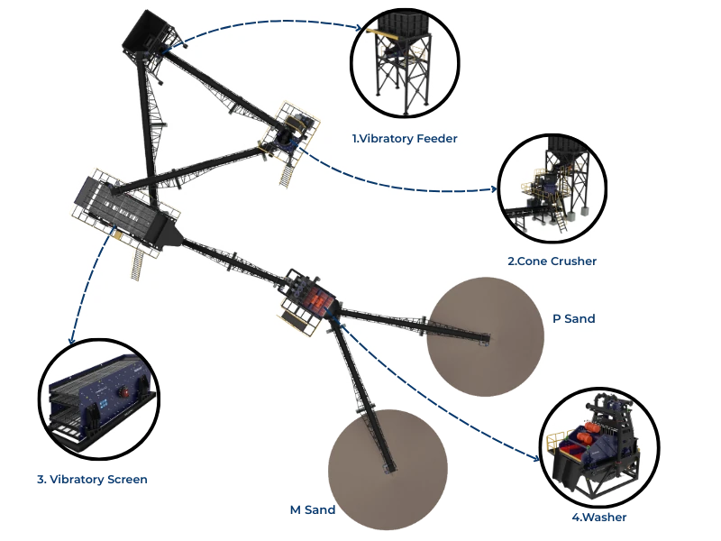
Cone crusher liner change is among the most critical maintenance operations in an aggregate plant—a 24-36 hour procedure that determines whether the crusher returns to service producing specification product or develops problems requiring immediate re-intervention. This step-by-step guide ensures safe, efficient liner changes that maximize liner life while protecting crusher components.
Pre-Change Preparation
Safety Requirements
- Lock out/tag out all energy sources (electrical, hydraulic, pneumatic)
- Verify zero energy state before entry
- Confined space procedures for chamber entry
- Fall protection when working at height
- Hot work permit if cutting/welding required
Parts and Tools Checklist
| Item | Quantity | Purpose |
|---|
| New bowl liner | 1 | Replacement |
| New mantle | 1 | Replacement |
| Backing compound | Per specification | Liner support |
| Torch ring/cutting equipment | As needed | Backing removal |
| Lifting equipment | Rated for liner weight | Liner handling |
| Torque wrench | Calibrated | Fastener tensioning |
Bowl Liner Removal
- Lower bowl assembly to access position (hydraulic system)
- Remove feed cone and associated components
- Verify backing condition before attempting removal
- Heat backing compound evenly around circumference
- Extract liner using lifting points or jack assemblies
- Inspect bowl surface for damage, cracks, or deformation
- Clean all surfaces of residual backing material
Mantle Removal
- Remove head nut using appropriate tooling
- Heat backing compound if mantle is backed
- Lift mantle using eye bolts or lifting lugs
- Inspect head surface for wear or damage
- Check head nut threads for damage
- Clean head surface completely
Surface Preparation
| Surface | Inspection Point | Action if Damaged |
|---|
| Bowl bore | Scoring, out-of-round | Machine if >1mm deviation |
| Head taper | Wear, galling | Build up and machine |
| Thread condition | Stripped, damaged | Chase threads or repair |
| Sealing surfaces | Flatness, finish | Re-machine if worn |
New Liner Installation
Mantle Installation
- Verify liner matches head taper specification
- Apply release agent to head surface (if backing)
- Position mantle centered on head
- Install torch ring or backing forms
- Pour backing compound per manufacturer instructions
- Allow backing to cure (typically 2-4 hours)
- Install and torque head nut to specification
Bowl Liner Installation
- Verify liner dimensions match bowl bore
- Apply release agent to bowl surface
- Lower liner into position
- Center liner in bowl
- Pour backing compound
- Allow curing before reassembly
Backing Compound Guidelines
| Factor | Specification | Consequence if Wrong |
|---|
| Mix ratio | Per manufacturer | Incomplete cure, weak bond |
| Pour temperature | 15-35°C typical | Too cold: won't cure; Too hot: flash set |
| Gap dimension | 3-6mm typical | Too thin: hot spots; Too thick: cracking |
| Cure time | 2-8 hours by type | Premature operation = liner movement |
Post-Installation Verification
| Check | Method | Acceptance |
|---|
| CSS setting | Lead ball measurement | Within specification |
| Liner clearance | Feeler gauge | Even gap around circumference |
| Head nut torque | Torque wrench | Per manufacturer spec |
| Lubrication system | Pressure/flow check | Normal values |
| Hydraulic function | Operational test | Smooth adjustment |
Break-In Procedure
- Run empty for 30 minutes monitoring temperatures
- Introduce feed at 50% rate for 2 hours
- Increase to 75% rate for 2 hours
- Full production after successful break-in
- Re-check CSS after first 8 hours of production
- Re-torque head nut after 24 operating hours
Conclusion
Proper liner change procedure protects your investment in new liners while ensuring safe return to production. Follow preparation checklists, respect backing cure times, and complete break-in procedures. Rushed liner changes create problems that require second interventions—taking the time to do it right the first time saves total downtime and protects crusher components for years of reliable service.