


When your conveyor system develops a spillage problem, the instinct is to blame worn skirting or belt tracking. But 70% of material spillage actually starts at the loading point—where material transfer dynamics, belt speed mismatches, and impact bed inadequacies create a chain reaction of problems that cost aggregate plants ₹15-30 lakhs annually in cleanup, wasted material, and premature component replacement.
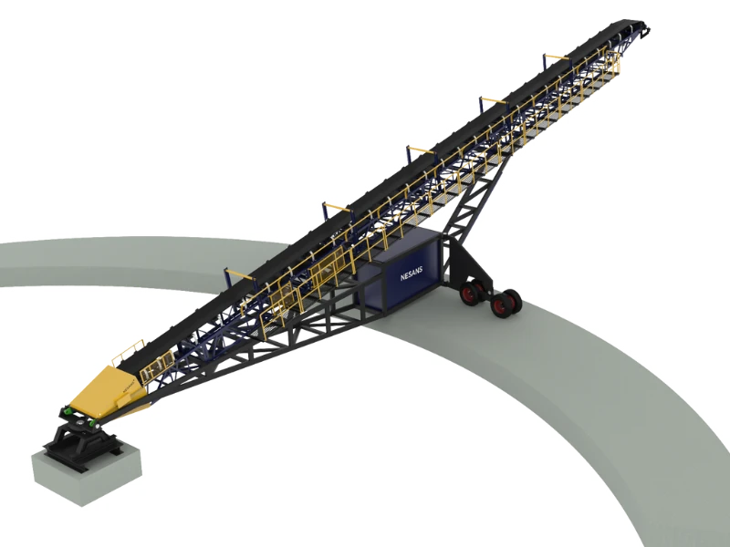
Belt conveyors are the arteries of material handling systems, yet they're frequently treated as passive transport mechanisms rather than precision-engineered systems requiring specific design parameters and proactive maintenance. A properly maintained conveyor system should operate cleanly with minimal spillage, consistent tracking, and predictable wear patterns. When spillage becomes chronic, it signals fundamental issues with loading dynamics, belt training, or sealing—issues that compound exponentially if left unaddressed.
This guide examines the critical relationship between loading point design and overall conveyor performance, focusing on practical solutions that eliminate spillage at the source while extending component life and reducing maintenance intensity.
Understanding Material Loading Dynamics
Material transfer onto a moving belt is a complex mechanical event governed by velocity matching, trajectory control, and impact absorption. The loading point is where static material from bins, chutes, or feeders transitions to dynamic transport on the belt—a moment of mechanical violence that determines downstream performance.
Proper loading requires three simultaneous conditions:
- Velocity Matching: Material horizontal velocity matches belt speed (±10%) to prevent sliding and abrasion
- Centered Loading: Material lands within the center third of belt width to prevent side loading and tracking issues
- Controlled Impact: Impact energy is absorbed by purpose-designed idlers or beds without belt damage
When any of these conditions fail, the consequences cascade: off-center loading causes belt wander, velocity mismatch creates sliding wear and spillage, excessive impact damages belt carcass and splices. A 1200mm belt receiving 150 TPH of 40mm aggregate with a 2 m/s velocity mismatch experiences 4× the abrasive wear compared to matched loading—reducing belt life from 24 months to 6 months.
Loading Point Design: The Foundation of Clean Operation
Transfer Chute Geometry
The transfer chute bridges the gap between discharge and belt, controlling material trajectory and velocity. Poor chute design is the primary cause of spillage and tracking problems.
Critical Design Parameters:
- Chute Angle: 60-70° from horizontal for free-flowing material, 50-55° for sticky/cohesive material
- Discharge Height: Position discharge point 300-450mm above belt to allow material deceleration without excessive impact
- Chute Width: 20-30% narrower than belt width to ensure centered loading with material spread
- Acceleration Length: Provide 1-1.5 meters of curved chute section to match material velocity to belt speed
⚠️ Impact on Spillage: A transfer chute positioned 800mm above a 2.5 m/s belt creates a velocity mismatch of 1.5-2 m/s, causing material to bounce and scatter. This results in 15-25% of fine material spilling beyond skirting, creating 8-12 tons of spillage per shift that must be cleaned manually. At ₹50/ton cleanup cost plus lost material value, this single loading point costs ₹4-6 lakhs monthly.
Impact Bed Configuration
The impact zone—where material first contacts the belt—experiences forces 3-5× greater than running sections. Standard carrying idlers cannot withstand these loads; dedicated impact beds are essential.
Impact Bed Design:
- Impact Idler Spacing: 150-200mm centers (vs. 1200mm for standard carry idlers)
- Impact Bar Configuration: Rubber impact bars 75-100mm wide × 50-75mm thick, supporting belt every 100-150mm
- Impact Bed Length: Minimum 3 meters for 150 TPH loading, extending 1-1.5m before and after material impact point
- Material Specification: 60-70 Shore A hardness rubber for impact absorption with structural support
On Nesans belt conveyor systems, impact beds are engineered with load-specific spacing and rubber durometer selection, ensuring impact energy dissipation without belt damage or splice failure.
⚠️ Impact on Belt Life: Operating with standard 1200mm-spaced carry idlers in the loading zone increases belt carcass damage by 400%, reducing belt life from 30 months to 7-8 months. For a 1200mm × 50m belt costing ₹8-10 lakhs, inadequate impact protection increases replacement frequency from every 2.5 years to every 8 months—raising annualized belt costs from ₹3.5 lakhs to ₹12 lakhs.
Belt Tracking: Preventing Mistracking at the Source
Root Causes of Belt Wander
Belt mistracking—when the belt drifts off-center on idlers—is a symptom, not a disease. The root causes are systematic and correctable:
- Off-Center Loading: Material landing outside the center third of belt width creates lateral forces that pull the belt toward the heavy side
- Frame Misalignment: Conveyor structure not level or square causes gravity-induced tracking errors
- Idler Misalignment: Carry or return idlers not perpendicular to belt travel create steering forces
- Material Buildup: Buildup on idler rolls or belt surface creates diameter differences that steer the belt
- Belt Damage: Uneven splice, edge damage, or carcass deformation creates differential stiffness
Systematic Tracking Correction
Step 1: Verify Loading Centerline
Measure material pile position on belt 2-3 meters past loading point. Material should be centered within ±150mm for a 1200mm belt. If off-center, adjust chute position or add material deflectors.
Step 2: Check Frame Alignment
Use a laser level or string line to verify conveyor structure is level transversely (side-to-side) within 3mm per meter. Longitudinal slope is acceptable, but frame twist causes persistent tracking issues.
Step 3: Align Idlers Systematically
Starting from the loading point, verify each idler is perpendicular to belt travel within 1-2mm. Use a square or laser guide. Never adjust idlers randomly—work systematically from feed end toward discharge.
Step 4: Implement Training Idlers Correctly
Training (steering) idlers should be placed strategically:
- One set 5-8 meters after loading point to correct initial tracking
- One set at 1/3 distance along conveyor length
- One set before discharge to ensure centered unloading
Avoid excessive training idlers—more than 4-5 sets indicates underlying problems that need correction, not compensation.
⚠️ Impact on Component Wear: A belt running 100mm off-center increases edge wear by 300%, reduces skirting seal effectiveness by 40%, and overloads one side of carry idlers by 60%. This accelerates skirting replacement from 12 months to 3-4 months (₹2-3 lakhs additional annual cost) and increases idler bearing failures by 50%.
Skirting and Sealing: The Last Line of Defense
Skirtboard Design Principles
Skirtboards contain material on the belt during loading and conveyance. Effective skirting requires both structural integrity and proper seal configuration.
Structural Requirements:
- Height: Skirting height should be 1.5-2× the maximum material lump size (300-400mm for 150mm rock)
- Length: Extend skirting 3-4 meters past the actual loading point to contain material scatter
- Mounting: Adjustable mounting brackets allowing 50-75mm of seal adjustment as wear occurs
- Material: 10-12mm steel plate or UHMW polymer for abrasion resistance and rigidity
Sealing System Configuration
The seal between skirtboard and belt determines spillage control effectiveness. Modern sealing systems use layered approaches:
Primary Seal (Top Layer):
Urethane or rubber seal material 25-40mm thick, durometer 60-70 Shore A. This seal carries 60-70% of the sealing load and wears fastest. Replace when compressed thickness reaches 50% of original.
Secondary Seal (Backing Layer):
Closed-cell foam or rubber 15-25mm thick, providing backup sealing and cushioning for the primary seal. Extends primary seal life by 40-60%.
Seal Pressure:
Maintain 50-80 N/linear meter of seal pressure—enough to prevent spillage without excessive belt friction. Over-tightening increases belt drag (energy waste) and accelerates both seal and belt cover wear.
⚠️ Impact on Fugitive Material: Worn sealing (>60% compressed) allows 3-8% of material to escape, creating 5-15 tons of spillage per day in a 200 TPH system. This generates ₹15,000-30,000 in daily cleanup costs, creates housekeeping and safety hazards, and contaminates return rollers—causing accelerated belt cover wear on the carrying side.
Material Buildup Prevention
Carry-Back and Return Strand Cleaning
Material adhering to the belt after discharge ("carry-back") returns on the underside, building up on return idlers and creating tracking problems and belt damage.
Primary Belt Cleaner (Discharge):
- Type: Diagonal or chevron scraper at 45-55° angle to belt travel
- Position: 100-200mm after discharge point while belt is still supported
- Blade Material: Urethane, 70-80 Shore A hardness for aggressive cleaning without belt damage
- Pressure: 200-300 N/meter blade length, adjusted to clean without excessive drag
Secondary Belt Cleaner (Safety Backup):
- Type: Brush or diagonal blade cleaner
- Position: 300-500mm after primary cleaner on declining belt span
- Purpose: Remove remaining fines and sticky material missed by primary cleaner
Nesans belt conveyor systems can be equipped with comprehensive cleaning packages including primary and secondary cleaners matched to specific material characteristics and operational conditions.
Return Idler Protection
Return idlers (supporting the unloaded belt underside) must be protected from material buildup:
- V-Plow Installation: Install V-plows before the first return idler to deflect any remaining carry-back
- Return Idler Spacing: 3-meter spacing minimum on return side; closer spacing increases buildup points
- Spiral Return Idlers: Self-cleaning spiral designs prevent material wrapping on roller surface
⚠️ Impact on Maintenance Intensity: Inadequate belt cleaning creates 50-100 kg/day of return strand buildup, necessitating weekly manual cleaning (4-6 labor hours) and causing premature return idler bearing failures. A single seized return idler can damage 3-5 meters of belt cover (₹50,000-80,000 repair cost) in 24-48 hours of operation.
Belt Speed and Loading Rate Optimization
Determining Optimal Belt Speed
Belt speed affects material trajectory, loading efficiency, and component wear. Faster isn't always better—each application has an optimal velocity range.
Speed Selection Guidelines:
- Coarse Aggregate (50-150mm): 2.0-3.5 m/s for balanced capacity and controlled loading
- Medium Material (10-50mm): 2.5-4.0 m/s for maximum efficiency
- Fine Material (<10mm): 2.0-3.0 m/s to minimize dust generation and spillage
- Steep Inclines (>15°): Reduce speed 20-30% to prevent material rollback
For a 1200mm belt carrying 200 TPH of 20-40mm aggregate, optimal speed is 2.8-3.2 m/s. Running at 4.0 m/s increases capacity by only 15% but increases spillage by 40%, impact forces by 60%, and dust generation by 80%.
Belt Loading Calculation
Belt capacity is governed by belt width, speed, and material characteristics. The standard formula:
Q = 3.6 × A × v × ρ × k
Where:
- Q = Capacity (TPH)
- A = Belt cross-section area (m²) - determined by belt width and troughing angle
- v = Belt speed (m/s)
- ρ = Material bulk density (t/m³)
- k = Loading factor (0.85-0.95 for well-designed loading)
For a 1200mm belt with 35° troughing, A ≈ 0.135 m². At 3.0 m/s carrying material with ρ = 1.6 t/m³:
Q = 3.6 × 0.135 × 3.0 × 1.6 × 0.9 ≈ 210 TPH
Running this system at 250 TPH (120% of design) reduces loading factor to 0.75, creating chronic spillage and increasing tracking difficulty.
Systematic Maintenance Schedule
Daily Inspections (15-20 minutes)
- Walk full conveyor length checking for spillage buildup, unusual sounds, or belt tracking deviations
- Verify belt cleaner blade contact—adjust if more than 30% material carry-back observed
- Check loading point for material scatter outside skirtboard boundaries
- Inspect for hot idlers (bearing failures)—thermal camera or hand check for excessive temperature
Weekly Maintenance (1-2 hours)
- Clean return idlers and remove any material buildup from belt underside
- Check and adjust skirting seal pressure—replace seals compressed beyond 60% original thickness
- Lubricate accessible bearing points per manufacturer specifications
- Verify belt tracking at 3-4 checkpoints along conveyor length
- Inspect belt splice condition—look for edge separation, loose fasteners (mechanical splices), or delamination
Monthly Inspections (2-3 hours)
- Full idler inspection—spin each roller checking for resistance or noise indicating bearing wear
- Measure belt cover thickness at 5-10 points along length—track wear patterns and project replacement timing
- Verify pulley lagging condition—replace if 30% worn or showing significant material buildup
- Check belt cleaner blade thickness—replace when worn to 40-50% original thickness
- Inspect belt for cuts, gouges, or carcass damage—repair small damage before it propagates
Quarterly Maintenance (4-6 hours)
- Measure and record belt tension—verify within manufacturer specifications (typically 1-3% of belt rating)
- Complete structural inspection—check for loose bolts, frame damage, or support degradation
- Verify alignment of all idlers using a laser or string line—correct any deviations >3mm
- Replace worn impact bed components—don't wait for complete failure
- Review maintenance logs and plan component replacements based on wear trends
Common Problems and Root Cause Solutions
Problem: Chronic Spillage at Loading Point
Symptoms: Material consistently spills beyond skirting, requiring daily cleanup.
Root Causes & Solutions:
- Velocity Mismatch: Adjust chute angle and length to match material velocity to belt speed
- Off-Center Loading: Add chute deflectors or adjust feeder position to center material stream
- Worn Skirting Seals: Replace seals and verify proper adjustment pressure (50-80 N/m)
- Excessive Loading Rate: Reduce feed rate to 85-95% of belt design capacity
Problem: Persistent Belt Mistracking
Symptoms: Belt runs off-center despite training idler adjustments.
Root Causes & Solutions:
- Structural Misalignment: Survey and level conveyor frame—correct twist and side-slope within 3mm/m
- Material Buildup on Idlers: Implement systematic cleaning program and improve belt cleaner performance
- Damaged Belt: Inspect full belt length for uneven splice, edge damage, or carcass issues—repair or replace
- Off-Center Loading: Correct material placement before attempting tracking adjustments
Problem: Excessive Carry-Back
Symptoms: Material adheres to belt after discharge, contaminating return strand.
Root Causes & Solutions:
- Ineffective Primary Cleaner: Increase blade pressure, adjust angle, or replace worn blade
- Sticky Material: Add secondary cleaner and consider belt spray system for moisture control
- Worn Belt Cover: Smooth surface allows better cleaning—rough cover retains material in surface texture
- Cleaner Position: Verify primary cleaner is 100-200mm after discharge while belt is still supported
ROI of Proper Loading Point Design
Investing in proper loading point configuration and systematic maintenance delivers measurable returns:
- Spillage Reduction: Eliminate 90-95% of material spillage, saving ₹12-25 lakhs annually in cleanup labor and lost material
- Belt Life Extension: Increase belt life by 40-60% through proper impact protection and tracking (₹4-7 lakhs annual savings on a typical 50m belt)
- Skirting and Seal Costs: Reduce replacement frequency from 3-4 months to 12-18 months (₹1.5-2.5 lakhs annual savings)
- Idler Bearing Life: Extend bearing life by 50-80% through cleaner operation and proper tracking (₹1-2 lakhs annual savings)
- Energy Efficiency: Reduce belt drag by 15-25% through elimination of material buildup and tracking friction (₹80,000-150,000 annual power savings)
- Maintenance Labor: Reduce cleaning and adjustment labor by 60-70% (₹3-5 lakhs annual savings)
For a 200 TPH aggregate plant, comprehensive loading point optimization and systematic maintenance delivers combined savings of ₹22-40 lakhs annually with payback periods of 6-12 months.
Conclusion: Loading Point Excellence as Operational Foundation
Material spillage isn't a belt conveyor problem—it's a loading point problem. The difference between a clean, efficient conveyor system and a chronic maintenance headache is determined in the first 5 meters after material transfer. Off-center loading, velocity mismatches, inadequate impact protection, and poor sealing create cascading problems that affect every downstream component.
Leading aggregate producers understand that conveyor systems are precision material handling equipment, not passive transport mechanisms. By applying engineering rigor to loading point design, implementing systematic tracking protocols, and maintaining proactive component replacement schedules, plants achieve 95%+ clean operation with predictable maintenance costs and extended component life.
Remember: Every hour spent optimizing your loading point saves 10 hours of corrective maintenance downstream. Start with centered, velocity-matched loading on proper impact beds, seal effectively with adjustable skirting, and maintain systematic inspection protocols. Material spillage is preventable—the question is whether you'll prevent it at the source or fight it at every idler throughout the system.
Ready to Eliminate Spillage and Extend Conveyor Life?
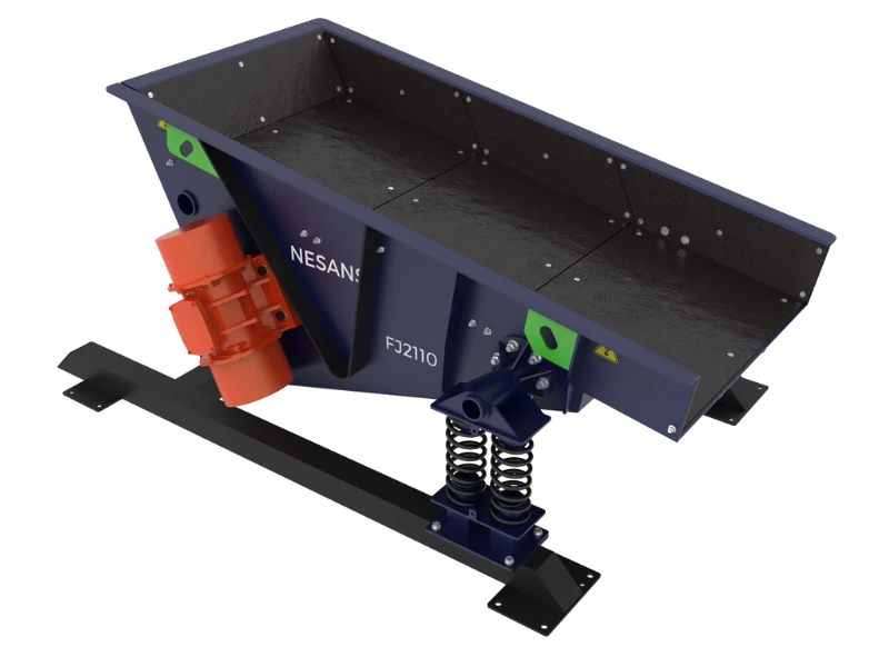
Nesans belt conveyor systems are engineered with optimized loading points, proper impact bed design, and comprehensive sealing systems. Our belt feeders provide controlled, centered material discharge for perfect loading conditions.
Contact our material handling specialists for a free conveyor system assessment and loading point optimization recommendations.