


Designing a 200 TPH aggregate plant requires balancing capital investment against operational efficiency, product quality against production flexibility, and equipment capability against site constraints. A well-designed plant achieves 85%+ mechanical availability, produces specification-compliant materials consistently, and generates returns that justify the ₹3-5 crore investment within 3-4 years. A poorly designed plant becomes a perpetual source of operational headaches, product quality issues, and maintenance expenses that erode profitability from day one.
The 200 TPH capacity represents a strategic sweet spot in Indian aggregate markets—large enough for commercial viability yet manageable in terms of capital, operational complexity, and environmental compliance. Plants at this capacity serve ready-mix concrete plants, infrastructure projects, and construction material traders while remaining within the technical capabilities of most regional equipment suppliers and maintenance teams.
This guide walks through every aspect of 200 TPH plant design, from feed material analysis through equipment selection, layout optimization, and operational considerations. Whether you're designing a greenfield installation or upgrading an existing plant, these principles ensure optimal performance from the first tonne processed.
Feed Material Analysis: The Foundation of Design
Every successful plant design begins with thorough understanding of the feed material. Equipment selection, circuit configuration, and even layout decisions flow from feed characteristics.
Critical Feed Parameters
| Parameter | Impact on Design | Testing Method | Typical Range for Granite | Typical Range for Basalt |
|---|---|---|---|---|
| Maximum Feed Size | Primary crusher selection | Direct measurement at quarry | 600-800mm | 500-700mm |
| Bulk Density | Conveyor and hopper sizing | IS 2386 Part 3 | 1.5-1.7 t/m³ (loose) | 1.6-1.8 t/m³ (loose) |
| Moisture Content | Screening efficiency, dust suppression | IS 2386 Part 3 | 1-5% | 1-4% |
| Compressive Strength | Crusher type and power | IS 9143 | 150-250 MPa | 200-350 MPa |
| Work Index (Bond) | Energy consumption prediction | Bond Work Index Test | 14-18 kWh/t | 16-22 kWh/t |
| Abrasion Index | Wear part life estimation | IS 2386 Part 4 | 0.2-0.5 (AI) | 0.3-0.6 (AI) |
| Fines Content | Scalping requirements | Sieve analysis | 5-15% passing 10mm | 3-10% passing 10mm |
| Clay/Silt Content | Washing requirements | IS 2386 Part 2 | 1-8% | 0.5-3% |
Product Requirements Analysis
Define target products before selecting equipment:
| Product | Size Range | Typical Market Price (₹/tonne) | IS Code Compliance | Production Priority |
|---|---|---|---|---|
| 40mm Aggregate | 20-40mm | 700-900 | IS 383:2016 | Low (limited market) |
| 20mm Aggregate | 10-20mm | 900-1200 | IS 383:2016 | High (RMC demand) |
| 12.5mm Aggregate | 6-12.5mm | 1000-1300 | IS 383:2016 | Medium |
| 6mm Aggregate | 3-6mm | 1100-1400 | IS 383:2016 | Medium |
| Crusher Dust | 0-5mm | 400-600 | — | Byproduct |
| Manufactured Sand | 0-4.75mm (Zone II) | 1200-1800 | IS 383:2016 | High value-add opportunity |
Capacity Calculation Fundamentals
A "200 TPH plant" requires careful definition. Consider:
- Nominal vs. Effective Capacity: Equipment is rated at continuous operation with optimal feed. Actual throughput is 80-90% of nominal.
- Operating Hours: 10-hour shifts, 300 days/year = 600,000 tonnes annual capacity (at 200 TPH effective)
- Bottleneck Identification: The plant's capacity equals its bottleneck capacity—typically secondary crushing or screening
- Product Split Impact: Different product mixes require different recirculation ratios, affecting net output
| Scenario | Gross Throughput | Recirculation Load | Net Saleable Product | Screen Load |
|---|---|---|---|---|
| Open Circuit (no reshaping) | 200 TPH | 0% | 200 TPH | 200 TPH |
| Closed Circuit (30% recirc) | 260 TPH | 60 TPH | 200 TPH | 260 TPH |
| High M-Sand (50% to VSI) | 300 TPH | 100 TPH | 200 TPH | 300 TPH |
Design Principle: Size equipment for peak recirculation scenarios, not minimum case.
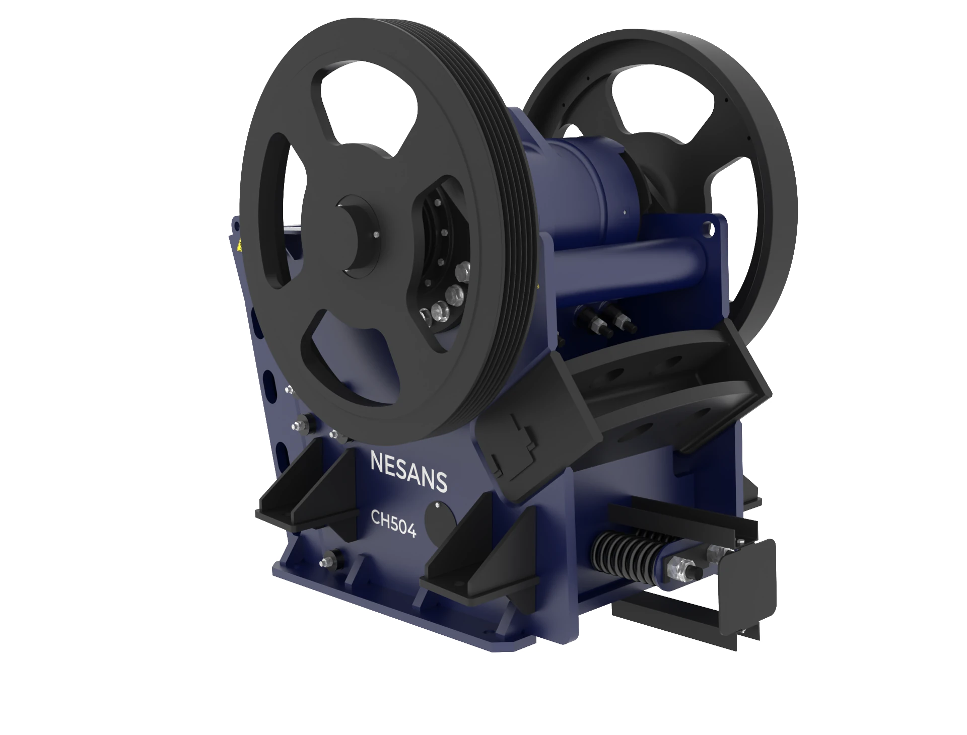
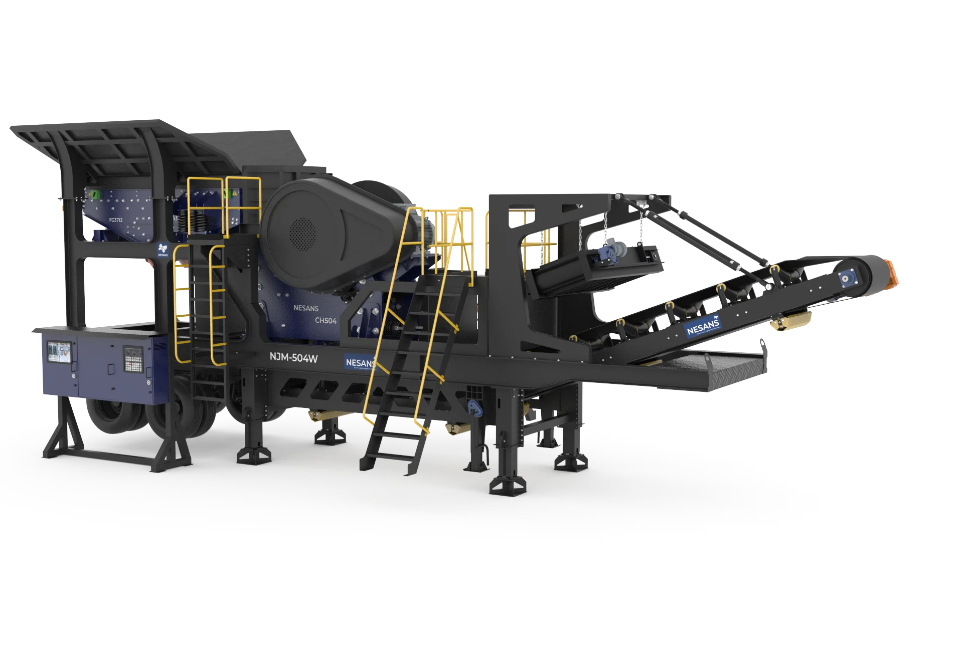
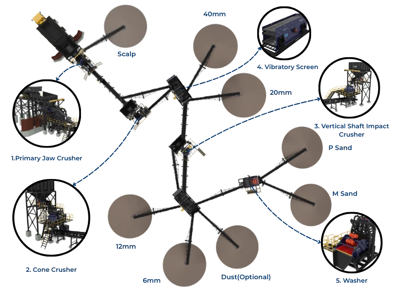
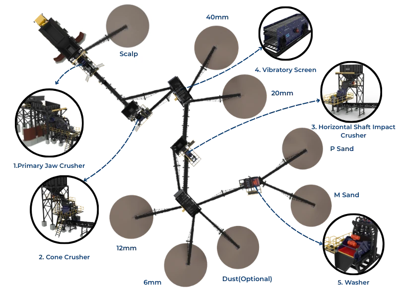
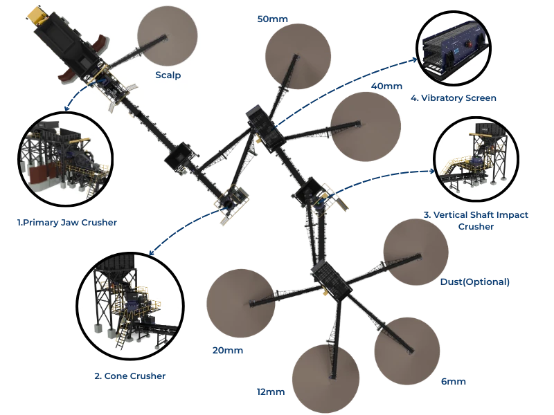
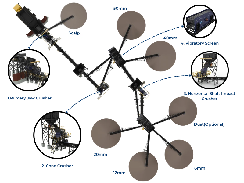
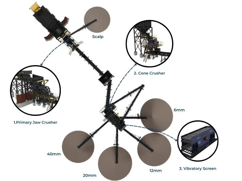
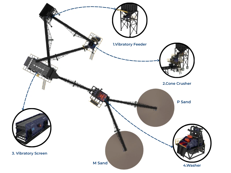
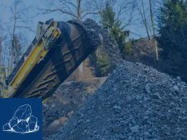
Equipment Selection: Primary Crushing Stage
Primary crushing reduces quarry-run material to sizes suitable for secondary processing. For 200 TPH plants, jaw crushers dominate due to cost-effectiveness and operational simplicity.
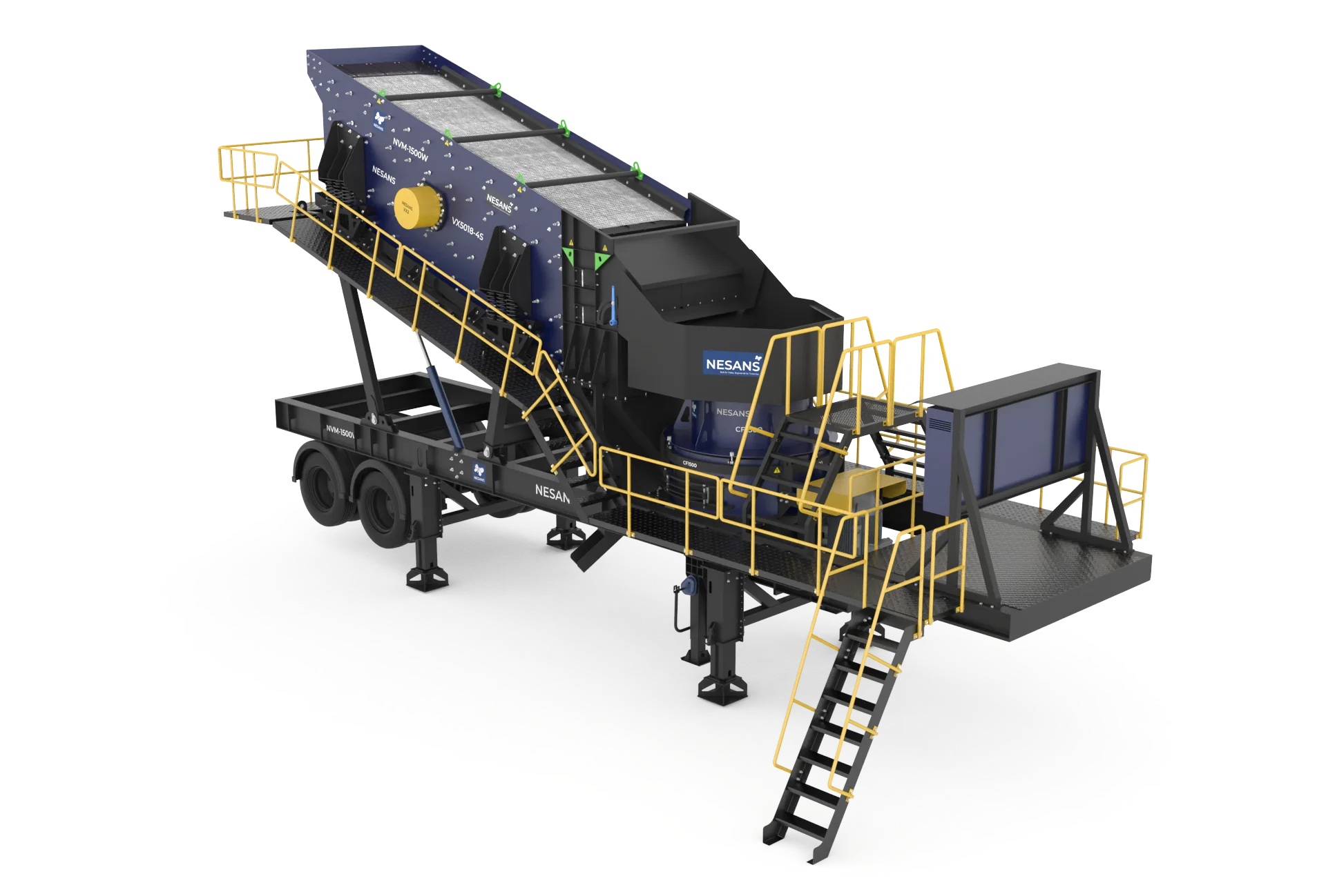
Jaw Crusher Sizing for 200 TPH
| Model Class | Feed Opening (mm) | Capacity Range (TPH) | Motor Power (kW) | Weight (tonnes) | Suitability |
|---|---|---|---|---|---|
| 36x24 / 900x600 | 900x600 | 80-150 | 55-75 | 15-18 | Undersized for consistent 200 TPH |
| 42x30 / 1050x750 | 1050x750 | 150-250 | 90-110 | 25-30 | Optimal for 200 TPH with typical feed |
| 48x36 / 1200x900 | 1200x900 | 250-350 | 132-160 | 40-50 | For larger feed or expansion potential |
Recommended Configuration
For reliable 200 TPH production with 600-700mm maximum feed:
- Primary Crusher: 42x30 inch (1050x750mm) single-toggle jaw crusher
- CSS Range: 100-150mm (adjustable for product size and capacity)
- Drive: 110 kW motor with flywheel energy storage
- Feed System: Vibrating grizzly feeder (1200x4500mm minimum)
Jaw Crusher Selection Criteria
| Criterion | Specification | Why It Matters |
|---|---|---|
| Feed Opening Width | >1.2x maximum feed size | Prevents bridging and feed rejection |
| Nip Angle | 19-23° | Affects grip on feed material, throughput |
| Stroke | 25-35mm for this size class | Longer stroke = higher throughput but more wear |
| Toggle Type | Single toggle preferred | Higher throughput, simpler maintenance vs double toggle |
| Bearing Type | Spherical roller bearings | Self-aligning, handles shock loads |
| CSS Adjustment | Hydraulic preferred | Faster adjustment, safer than wedge systems |
| Frame Construction | Cast steel or fabricated plate | Cast more rigid; fabricated easier to repair |
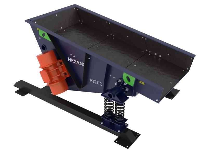
Grizzly Feeder Requirements
The grizzly feeder controls feed rate and removes undersized material before primary crushing:
| Parameter | Specification for 200 TPH | Notes |
|---|---|---|
| Pan Width | 1200-1400mm | Match to truck body width |
| Total Length | 4500-5500mm | Including grizzly section |
| Grizzly Bar Spacing | 75-125mm typical | Scalp undersized material before crusher |
| Drive Type | Eccentric shaft or electromagnetic | Eccentric more robust for heavy duty |
| Motor Power | 15-22 kW | Variable frequency drive for rate control |
| Hopper Capacity | 10-15 m³ minimum | Buffer between truck tips |
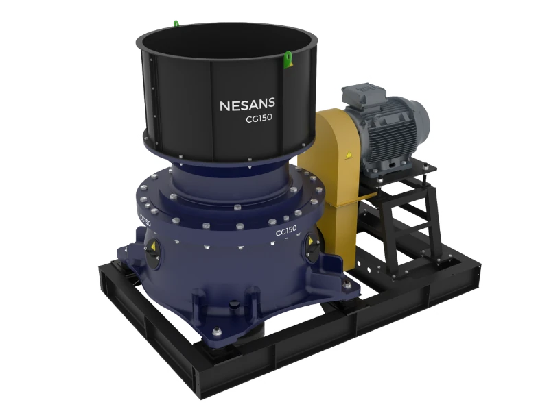
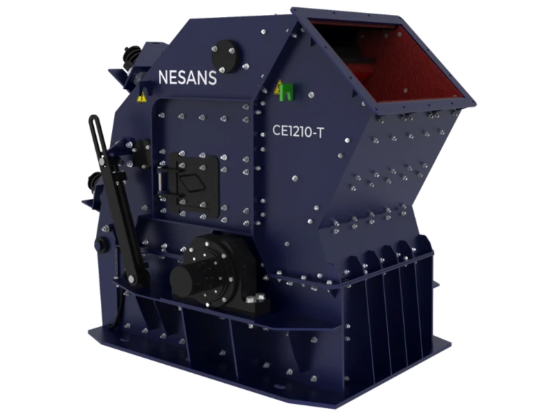
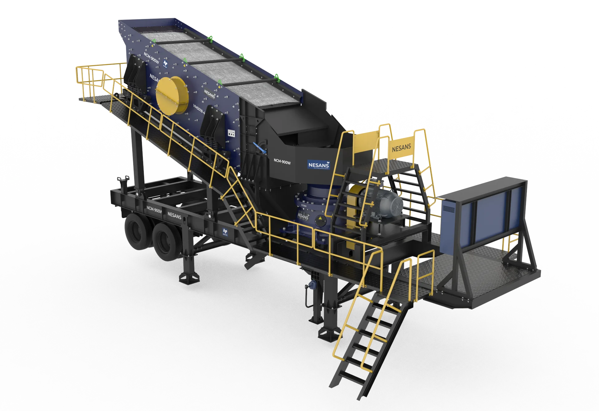
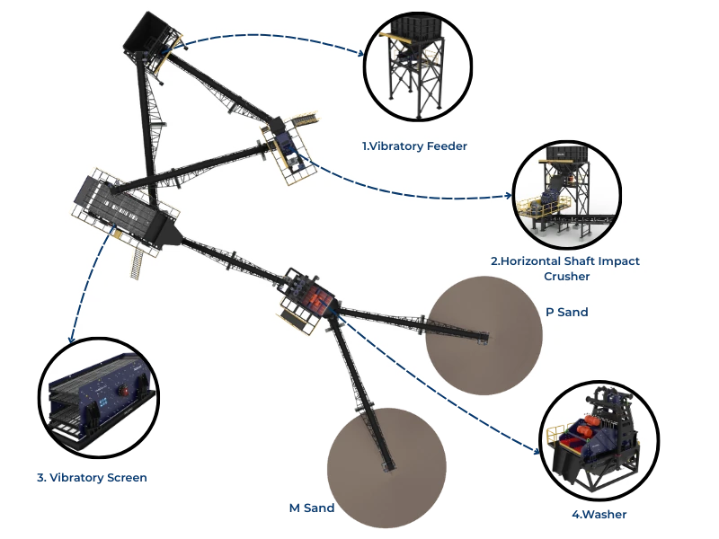
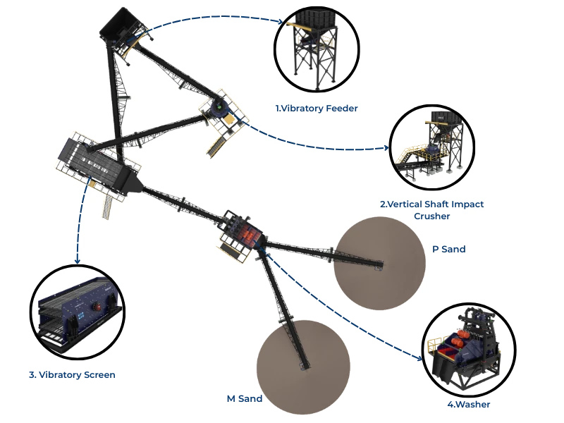
Equipment Selection: Secondary Crushing Stage
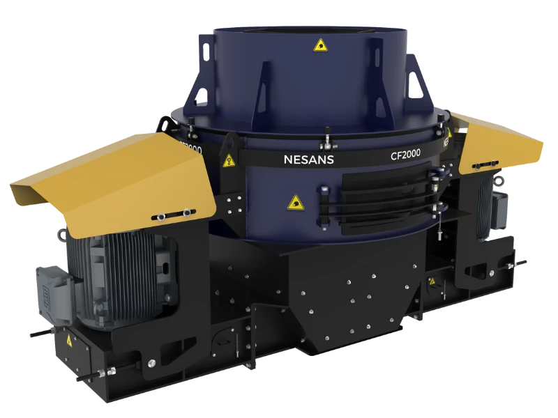
Secondary crushing determines product gradation, shape quality, and overall plant capacity. Equipment choice here has the greatest impact on final product value.
Secondary Crusher Options Comparison
| Crusher Type | Cone Crusher | HSI (Horizontal Shaft Impact) | VSI (Vertical Shaft Impact) |
|---|---|---|---|
| Reduction Ratio | 4:1 to 6:1 | 10:1 to 25:1 | 3:1 to 8:1 |
| Product Shape | Good (cubical) | Excellent (cubical) | Best (highly cubical) |
| Fines Generation | Moderate | High | Very High |
| Wear Cost (₹/tonne) | ₹8-15 | ₹12-25 | ₹15-35 |
| Capital Cost | ₹60-90 lakhs | ₹50-70 lakhs | ₹55-85 lakhs |
| Power Consumption | 0.8-1.2 kWh/t | 1.0-1.8 kWh/t | 1.5-2.5 kWh/t |
| Feed Size (max) | 150-200mm | 200-400mm | 40-60mm |
| Best Application | Hard, abrasive rock | Medium-hard rock, high reduction needed | Sand making, final shaping |
Recommended Secondary Configuration for 200 TPH
For most granite/basalt operations producing aggregate and M-sand:
Option A: Cone-Based Circuit (Best for hard, abrasive material)
- Secondary Crusher: 48" (1200mm) cone crusher, 200-250 TPH capacity
- CSS Range: 20-40mm
- Motor: 200-250 kW
- Tertiary Crusher (if needed): VSI for M-sand production
Option B: HSI-Based Circuit (Best for medium-hard rock, cost sensitivity)
- Secondary Crusher: 1315 or 1320 HSI, 200-300 TPH capacity
- CSS/Gap: 25-50mm
- Motor: 160-200 kW
- Note: Higher wear costs but lower capital, excellent product shape
Cone Crusher Specifications for 200 TPH
| Specification | Standard Head | Short Head | Selection Notes |
|---|---|---|---|
| Feed Size (max) | 150-200mm | 75-125mm | Short head for tertiary applications |
| CSS Range | 19-50mm | 10-25mm | Hydraulic adjustment recommended |
| Capacity at CSS 25mm | 180-220 TPH | 120-160 TPH | Standard head for secondary |
| Liner Type | Manganese steel | Manganese steel | 20-22% Mn for hard rock |
| Crushing Chamber | Fine, Medium, Coarse options | Extra Fine, Fine, Medium | Match to feed and product |
| Tramp Release | Hydraulic accumulator system | Hydraulic accumulator system | Essential for uncrushable protection |
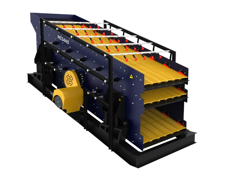
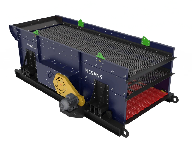
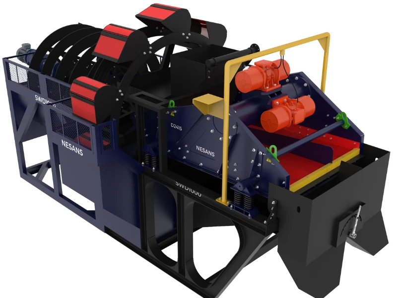
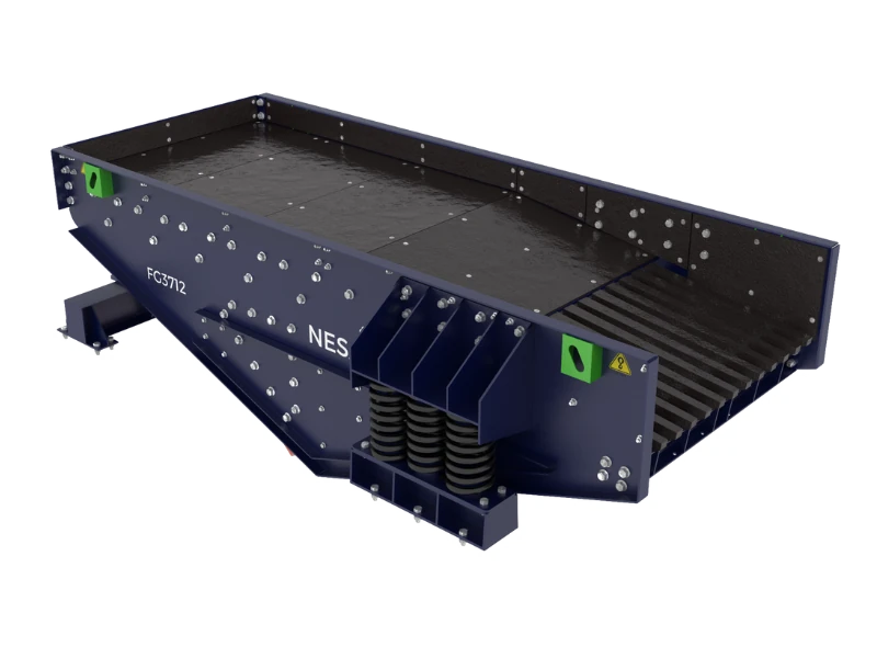
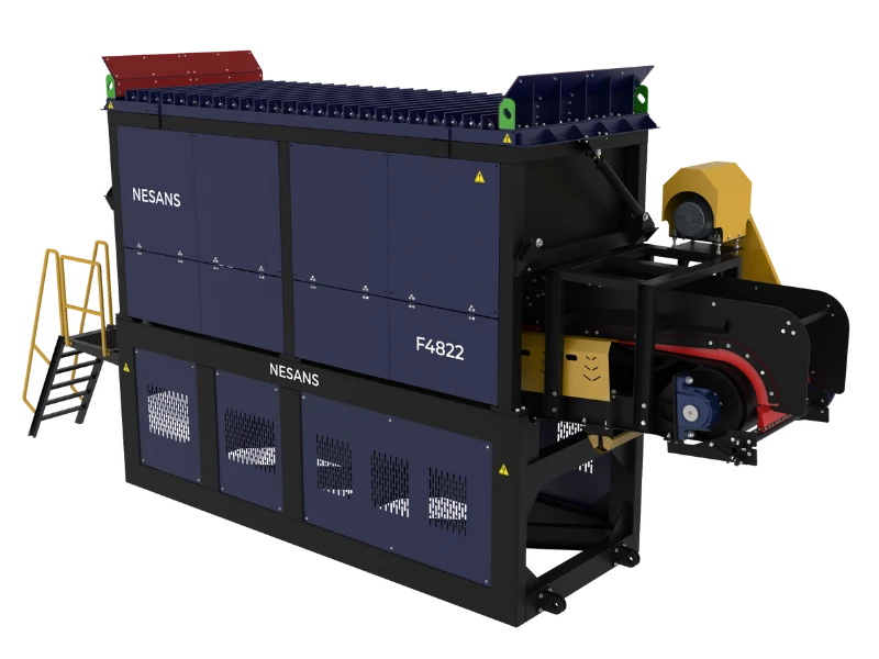
Screening Equipment Selection
Screens are often the bottleneck in aggregate plants. Proper sizing is critical for achieving rated capacity.
Screen Capacity Calculation
Screen capacity depends on:
- Deck Area: More area = more capacity
- Aperture Size: Larger openings = higher capacity
- Material Characteristics: Wet, sticky, or elongated particles reduce capacity
- Deck Position: Top deck sees full load; lower decks handle reduced volumes
- Oversize/Undersize Ratio: High percentage of near-size material reduces efficiency
Basic capacity calculation:
Capacity (TPH) = Base Capacity × Area × K1 × K2 × K3 × K4 × K5

Where:
- Base Capacity: TPH/m² at given aperture (from manufacturer charts)
- K1: Correction for % oversize (material larger than aperture)
- K2: Correction for % half-size (material smaller than half aperture)
- K3: Correction for deck position (1.0 top, 0.9 second, 0.8 third)
- K4: Correction for wet screening (1.0 dry, 0.75 wet)
- K5: Correction for shape (1.0 cubical, 0.85 flaky)
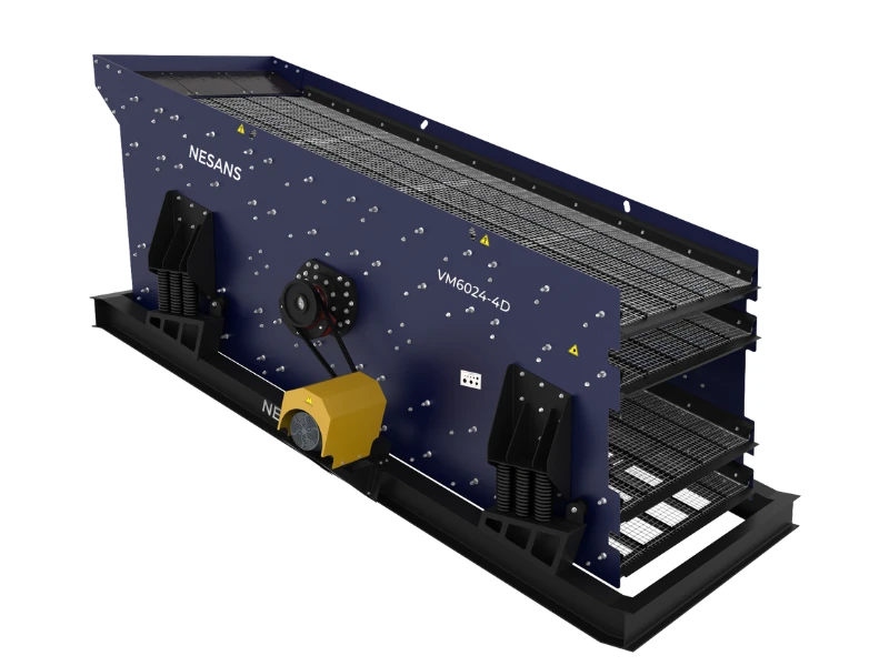
Recommended Screens for 200 TPH
| Screen Position | Type | Size (mm) | Decks | Motor (kW) | Typical Apertures |
|---|---|---|---|---|---|
| Primary (Scalping) | Inclined Vibrating | 1500x4800 | Single | 15-22 | 75-125mm |
| Secondary Classification | Inclined Vibrating | 1800x6000 | 3-deck | 30-45 | 40mm, 20mm, 10mm |
| Tertiary/Final | Inclined Vibrating | 1500x4800 | 2-deck | 22-30 | 6mm, 3mm (or washing) |
Screen Specification Details
| Parameter | Specification | Design Rationale |
|---|---|---|
| Inclination | 15-20° (inclined type) | Steeper = faster travel, lower efficiency; Flatter = higher efficiency, lower capacity |
| Stroke | 8-12mm | Longer stroke for coarser material |
| Speed | 800-1000 RPM | Higher for fine material, lower for coarse |
| G-Force | 3.5-5.0 G | Higher G improves stratification but increases wear |
| Screen Media | Wire mesh, polyurethane, or rubber | Wire mesh cheapest; poly/rubber longer life, quieter |
| Deck Clearance | Minimum 250mm between decks | Allows material flow and prevents bridging |
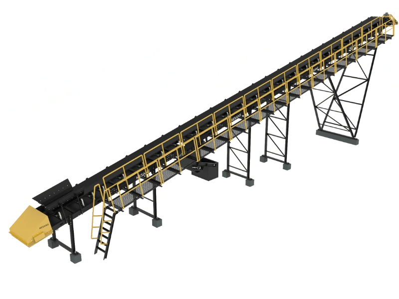
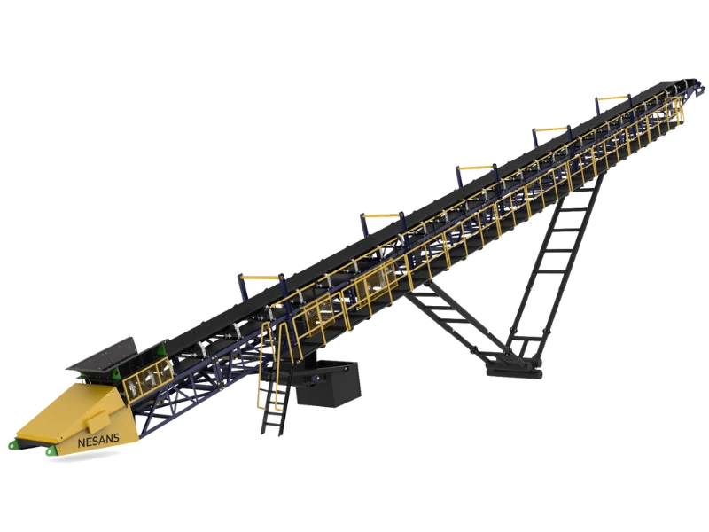
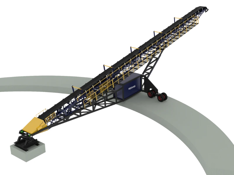
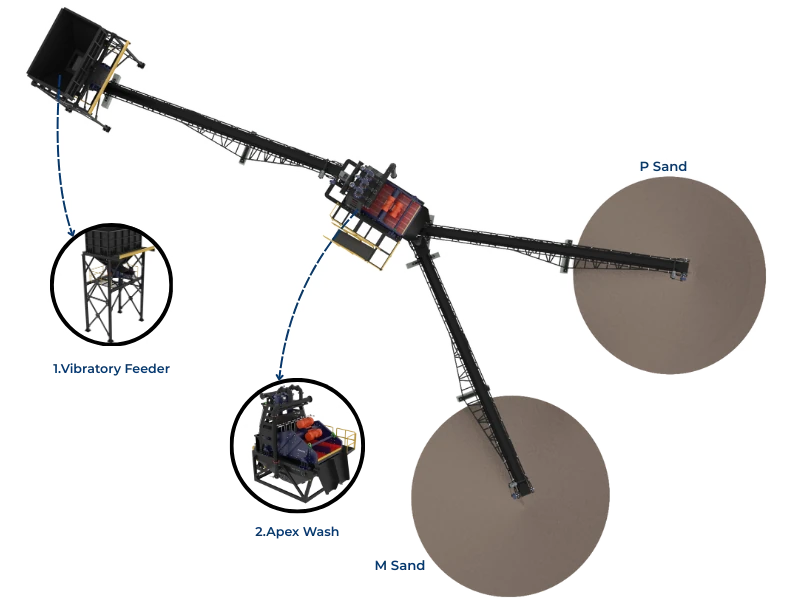
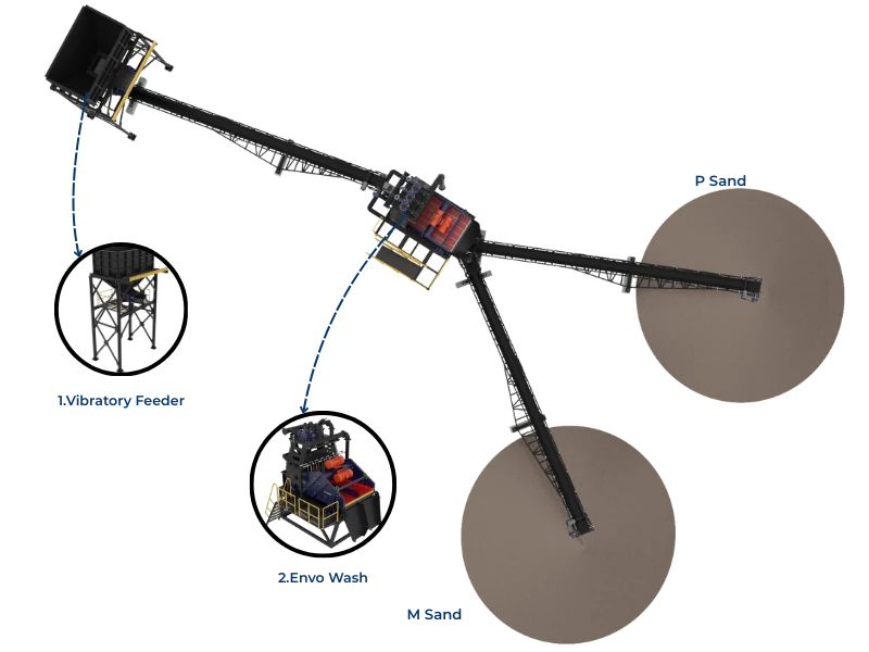
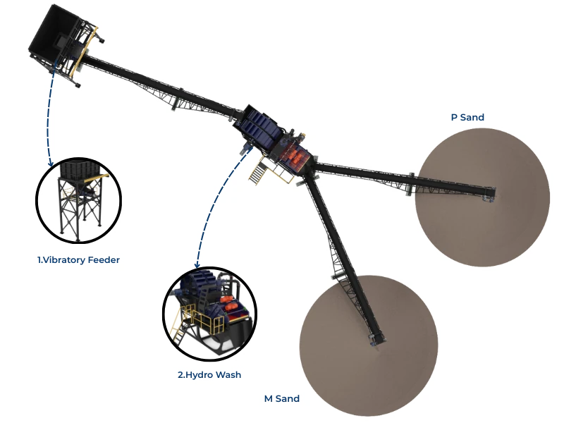
Conveyor System Design
Conveyors connect processing units and account for 15-20% of plant capital cost. Proper design ensures reliable material flow without spillage or damage.
Conveyor Specification Summary
| Conveyor Position | Belt Width (mm) | Speed (m/s) | Motor (kW) | Typical Length (m) | Inclination |
|---|---|---|---|---|---|
| Jaw Discharge | 800-1000 | 1.5-2.0 | 15-22 | 20-30 | 0-12° |
| Cone Feed | 800-1000 | 1.5-2.0 | 15-22 | 15-25 | Variable |
| Screen Feed | 1000-1200 | 1.5-2.0 | 22-30 | 20-40 | 15-18° |
| Product Stockpile | 650-800 | 2.0-2.5 | 11-15 | 25-40 | 18-20° |
| Recirculation | 650-800 | 2.0-2.5 | 11-15 | 30-50 | 18-20° |
Conveyor Design Principles
- Belt Capacity: Design for 70-80% of theoretical capacity to prevent spillage
- Belt Speed: Higher speeds reduce belt width requirement but increase wear and dust
- Transfer Points: Use stone boxes or rock ladders to control impact and velocity
- Skirting: Minimum 1.5m length at loading points, adjustable for belt wear
- Troughing Angle: 35° standard; 45° for increased capacity at same width
- Belt Grade: PN/NN 250-315 for standard service; EP grade for higher tension
Critical Transfer Point Design
| Parameter | Design Rule | Consequence of Poor Design |
|---|---|---|
| Drop Height | Minimize; <1.5m preferred | Belt damage, dust generation, material degradation |
| Chute Angle | >60° from horizontal | Material buildup, blockage |
| Loading Direction | Material velocity aligned with belt travel | Belt wear, spillage, tracking problems |
| Impact Bed | Install at all high-impact loading points | Belt damage, idler failure |
| Belt Cleaners | Primary + secondary at head pulley | Carryback, idler buildup, tracking issues |
Plant Layout Optimization
Layout design balances material flow efficiency against site constraints, maintenance access, and future expansion capability.
Layout Design Principles
- Gravity Flow: Use natural elevation changes to minimize conveyor lifts and power consumption
- Shortest Path: Minimize conveyor lengths to reduce capital and operating costs
- Maintenance Access: Provide crane/forklift access to all major components
- Stockpile Capacity: Size stockpiles for 1-2 days production minimum
- Traffic Flow: Separate loading and dumping traffic patterns
- Expansion Space: Reserve area for additional crushers, screens, or products
- Environmental: Position dust sources downwind; plan drainage for runoff
Typical 200 TPH Layout Dimensions
| Area | Dimension | Notes |
|---|---|---|
| Overall Plant Footprint | 80m x 100m minimum | Includes circulation roads |
| Primary Crushing Area | 15m x 20m | Hopper, feeder, jaw, discharge |
| Secondary/Screening Area | 25m x 30m | Cone, screens, surge bins |
| Stockpile Area | 50m x 60m | 5 products + crusher dust |
| Each Product Stockpile | 15-20m base diameter | 500-1000 tonne capacity each |
| Truck Loading Area | 6m wide lanes, 25m turn radius | For 20-tonne trucks |
| Maintenance Area | 15m x 20m covered | Workshop, stores, laydown |
Elevation Design
For optimal gravity flow with minimal conveyor angles:
- Primary Hopper: Ground level (truck tip) + 3-4m elevation for feeder
- Jaw Crusher Discharge: ~1.5m below jaw centerline
- Surge Bin before Secondary: Position for gravity feed to cone at correct level
- Main Screen: Elevated 6-8m for product separation
- Stockpile Height: 8-12m maximum for radial stackers
Electrical System Design
Power Requirements Summary
| Equipment | Quantity | Motor Power (kW) | Total Connected (kW) |
|---|---|---|---|
| Jaw Crusher | 1 | 110 | 110 |
| Grizzly Feeder | 1 | 18.5 | 18.5 |
| Cone Crusher | 1 | 200 | 200 |
| Vibrating Screens | 2 | 37 | 74 |
| Conveyors (8 units) | 8 | 15 (avg) | 120 |
| VSI (if installed) | 1 | 250 | 250 |
| Ancillary (pumps, lighting) | Various | — | 50 |
| Total Connected Load | 822.5 kW | ||
| Maximum Demand (0.7 factor) | ~575 kW |
Transformer and Distribution
- Transformer Sizing: 750 kVA minimum for 200 TPH without VSI; 1000 kVA with VSI
- Voltage: 11 kV incoming, 415V distribution typical
- Power Factor: Install capacitor bank to maintain >0.95 PF and avoid penalties
- Starting Method: DOL acceptable for <75 kW; soft starters for crushers and large conveyors
- Emergency Stop: Plant-wide E-stop system with pull-cord along conveyors
Motor Control Center (MCC)
| Feature | Requirement | Benefit |
|---|---|---|
| Enclosure | IP55 minimum outdoor; IP42 if enclosed room | Dust and water protection |
| Starters | VFD for feeders; DOL/Star-Delta for conveyors | Rate control, reduced inrush |
| Interlocks | Sequential start, reverse sequence stop | Prevents material buildup on stopped conveyors |
| Monitoring | Current, voltage, power factor display | Operational awareness |
| Protection | Overload, earth fault, phase failure | Equipment and personnel safety |
Control System Design
Automation Levels
| Level | Features | Cost Impact | Suitability |
|---|---|---|---|
| Basic | Local start/stop, manual rate control | Baseline | Simple operations, low volume |
| Semi-Automatic | Interlocked sequencing, basic PLC | +₹10-15 lakhs | Standard commercial plants |
| Fully Automatic | Automatic level control, production optimization | +₹25-35 lakhs | High-volume, unmanned operation goals |
| Smart Plant | Remote monitoring, predictive maintenance, AI optimization | +₹50-80 lakhs | Premium operations, multiple sites |
Recommended Interlocks
- Startup Sequence: Stockpile conveyors → product conveyors → screens → crusher feed conveyor → crusher → feeder
- Shutdown Sequence: Reverse of startup with time delays for clearing
- Level Control: Stop feeder when surge bin reaches high level, restart at low level
- Crusher Protection: Stop feed on high crusher current, CSS limit, or low lube pressure
- Belt Protection: Stop preceding equipment on belt slip, rip detection, or misalignment
Cost Estimation
Capital Cost Breakdown
| Category | Cost Range (₹ Lakhs) | % of Total | Notes |
|---|---|---|---|
| Primary Crushing (Jaw + Feeder) | 45-65 | 12-15% | Including hopper structure |
| Secondary Crushing (Cone) | 60-90 | 18-22% | Add ₹50-80 lakhs for VSI |
| Screens (2-3 units) | 35-55 | 10-13% | Including structures |
| Conveyors (8-10 units) | 50-80 | 15-18% | Including drives and supports |
| Electrical System | 45-65 | 12-15% | Transformer, MCC, cabling |
| Steel Structures | 30-50 | 8-12% | Platforms, supports, chutes |
| Civil Works | 40-60 | 10-15% | Foundations, roads, buildings |
| Installation & Commissioning | 25-40 | 6-10% | Labor, testing, training |
| Total (without VSI) | 330-505 | 100% | ₹3.3-5.0 crore |
| Total (with VSI) | 380-585 | — | ₹3.8-5.85 crore |
Operating Cost Estimation
| Cost Component | ₹/Tonne Processed | Monthly at 200 TPH × 300 hrs | Notes |
|---|---|---|---|
| Electrical Energy | ₹25-40 | ₹15-24 lakhs | At ₹7-8/kWh, 3-5 kWh/t |
| Wear Parts | ₹15-30 | ₹9-18 lakhs | Jaw dies, cone liners, screen media |
| Diesel (if applicable) | ₹5-15 | ₹3-9 lakhs | Generators or mobile equipment |
| Labor (6-8 persons) | ₹8-12 | ₹5-7 lakhs | Operators, loader, maintenance |
| Maintenance (parts, consumables) | ₹10-15 | ₹6-9 lakhs | Belts, idlers, bearings, oils |
| Overhead (admin, insurance, etc.) | ₹5-10 | ₹3-6 lakhs | Site costs, compliance |
| Total Operating Cost | ₹68-122 | ₹41-73 lakhs | Varies significantly with utilization |
Installation Sequence
Recommended Installation Order
- Site Preparation (Week 1-2): Survey, clearing, drainage, access roads
- Civil Works (Week 2-6): Foundations for all equipment, starting with crushers
- Primary Section (Week 5-8): Hopper, feeder, jaw crusher, discharge conveyor
- Secondary Section (Week 7-10): Surge bin, cone crusher, conveyors
- Screening Section (Week 9-12): Screen installation, product conveyors
- Electrical (Week 8-14): Parallel with mechanical, transformer early
- Commissioning (Week 13-16): Individual testing, system integration, load testing
Commissioning Checklist
Pre-Commissioning Verification
- All mechanical installation complete, bolts torqued to specification
- Electrical connections complete, insulation tested
- Lubrication systems filled, bearings greased
- Guards installed, emergency stops functional
- Conveyor belts tracked, scrapers adjusted
- Screen media installed correctly
- Crushing chamber CSS set to specification
No-Load Testing
| Equipment | Duration | Check Points |
|---|---|---|
| Conveyors | 4 hours each | Tracking, speed, motor current, bearing temps |
| Screens | 4 hours each | Stroke, speed, uniformity, structural resonance |
| Jaw Crusher | 8 hours | Bearing temps, toggle action, flywheel balance |
| Cone Crusher | 8 hours | Oil pressure, bearing temps, gyration uniformity |
Load Testing Protocol
- 25% Capacity (8 hours): Verify all systems functioning, note baseline readings
- 50% Capacity (16 hours): Check temperatures stabilizing, product quality
- 75% Capacity (24 hours): Sustained operation, fine-tune settings
- 100% Capacity (48 hours): Performance verification against design
Conclusion
A 200 TPH aggregate plant represents a significant investment demanding careful engineering at every stage. Success depends on thorough understanding of feed material characteristics, systematic equipment selection based on processing requirements rather than equipment availability, and layout optimization that balances operational efficiency against practical constraints.
The equipment combinations recommended here—42x30 jaw crusher feeding a 48" cone with 3-deck screening—represent proven configurations delivering reliable 200 TPH production with granite and basalt materials. Adding VSI crushing transforms the plant from a basic aggregate producer into a premium manufactured sand facility, commanding significantly higher product prices that justify the additional capital investment.
Invest time in the design phase. Every hour spent optimizing layout, specifying correct equipment, and planning installation sequences saves days of troubleshooting during commissioning and years of operational inefficiency. The most profitable plants aren't those with the most expensive equipment—they're those where every component works in harmony because the design team understood material flow, capacity balancing, and operational reality from the beginning.